Difference between revisions of "GeoLink Mounting"
(→Unmounting) |
(→Unmounting) |
||
| Line 65: | Line 65: | ||
'''Always try to pull out double sided tape first, not the module.''' Lastly rotate with the module until the double sided tape will peel off. | '''Always try to pull out double sided tape first, not the module.''' Lastly rotate with the module until the double sided tape will peel off. | ||
<br/> | <br/> | ||
| − | {{Quote|'''Never pull the module in any way when mounted with double sided tape! This could bent or crack | + | {{Quote|'''Never pull the module in any way when mounted with double sided tape! This could bent or crack the plastic enclosure.'''}} |
<br/> | <br/> | ||
Revision as of 17:59, 29 May 2018
Correct mounting is the most important for achieving optimal operating condition. If done improperly GeoLink will be unable to work with great precision or in the worst case some functionality could be even not usable.
Please take special care in order to perform the following steps thoroughly.
Contents
1 Mounting on your helicopter
As of now, module must be mounted always horizontally so that GeoLink logo is at the top. You can select from two positions:
- Horizontal (0°) - connector is pointing to main rotor
- Horizontal (180°) - connector is pointing to tail rotor
Before actual mounting please review Alignment section.
1.1 Where to mount
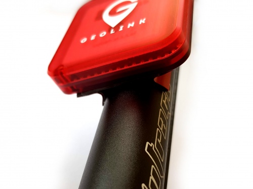
GeoLink module should be mounted ideally at the TAIL BOOM. This is usually the best position for achieving optimal performance. Optimal position should meet the following:
- It is at least 5cm far from a rigid conductive parts such as carbon frame
- It is at least 5cm far from any electronics (especially servos)
- It is at least 8cm far from an electric motor
- It has clear sky visibility
- It is perfectly horizontally aligned
Choose a position which is not too far, so that provided cable is long enough. Placing module too far on the boom could lead to bad Center of Gravity of the model.
1.2 How to mount
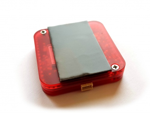
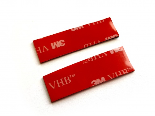
Module attachment is normally performed by provided Double Sided tape. Provided tape has extremely good bonding properties so that it can hold more than better even when only two rails of the tape are used.
Some helicopters are equipped with a fuselage instead of boom. In that case there is chance you will have to spend more time to achieve flat mounting surface.
Optionally you can use a third party mounting support designed for GPS modules.
Never mount GeoLink directly on a thick metallic parts, near a motor or any servo.
Each circuit containing antennas is very carefully designed to achieve correct impedance. Impedance is electrical property which is directly determining performance of antenna. Impedance is changing immediately by placing any parts close to the circuit, especially near antenna. Because PCB is acting as a part of GPS antenna any change to the PCB, including screws has noticeable impact. Thus we highly do not recommend doing any hardware changes to GeoLink module.
1.3 Mounting with provided tape
1. Take the first piece of tape and glue it approximately in the middle.
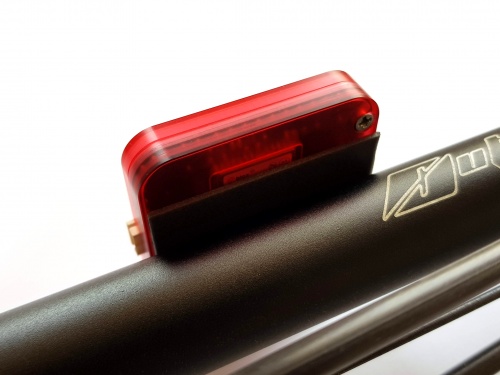
2. Attach the module at the tail boom.
3. Divide second piece of tape.
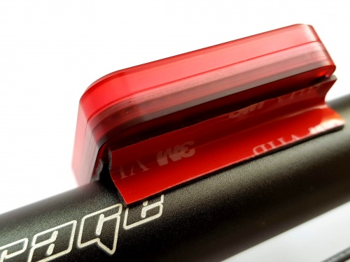
4. While holding folded tape in two fingers insert it between module and boom to create support (from both sides). With a finger or a tool try to insert both pieces as far as possible so that adhesive surfaces are holding well.
The tape will shortly adhere on the surface tightly and can't be reused anymore.
1.4 Unmounting
In some cases pilot might need to remove GeoLink from a model, for example during a repair. When provided double sided is used a special care must be taken!
Always try to pull out double sided tape first, not the module. Lastly rotate with the module until the double sided tape will peel off.
Never pull the module in any way when mounted with double sided tape! This could bent or crack the plastic enclosure.
2 Wiring
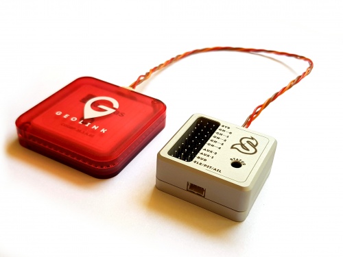
Wiring is done through one JST to JST cable with length of 22cm which is supplied with GeoLink. Longer cable is possible and will be available. For GPS itself a shorter cable is better, because any additional cables attached to the module and Spirit unit could distort the signal.
μSpirit SAT - Satellite port Spirit Primary satellite port Spirit Pro Secondary satellite port
3 Alignment
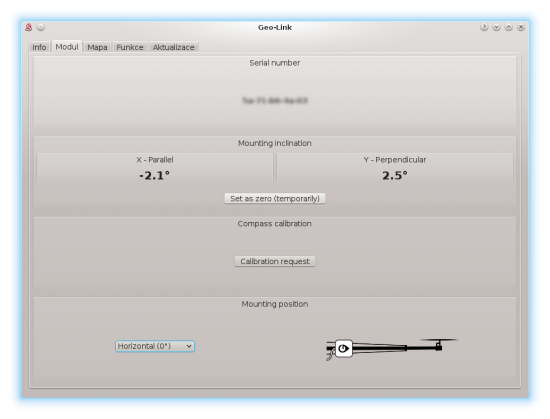
Since it is uneasy to visually align the module perfectly, the GeoLink has built-in digital level in the Spirit Settings. There you can see how to align the module and perform a necessary adjustments.
3.1 Alignment procedure
Alignment can be done prior the mounting or even later, as needed.
- Connect GeoLink and Spirit unit with provided cable (while GeoLink being not mounted yet).
- Power up the Spirit unit.
- After initialization start the Spirit Settings software.
- Open General tab - GeoLink module settings.
- Move to the Module tab there.
- Place GeoLink at a flat, aligned horizontal surface anywhere on your model in order to get a precise reference. (for example the Spirit unit)
- Click Set as zero (temporarily) button to reset the angle.
- Move GeoLink to a desired mounting position.
- Mount it with provided double sided tape at position ideally with 0° deflection.

