Difference between revisions of "GeoLink Configuration/ru"
(Created page with "Когда модель направлена на '''север''', вы должны увидеть примерно '''90 +/- 4 °'''. Величина не должна б...") |
(Created page with "Мы рекомендуем не использовать смартфоны в качестве компаса. Они обычно не откалиброваны вообщ...") |
||
| Line 19: | Line 19: | ||
Когда модель направлена на '''север''', вы должны увидеть примерно '''90 +/- 4 °'''. Величина не должна быть далека от этого значения. | Когда модель направлена на '''север''', вы должны увидеть примерно '''90 +/- 4 °'''. Величина не должна быть далека от этого значения. | ||
| − | {{Info|[[File:Info.png|18px|]] | + | {{Info|[[File:Info.png|18px|]] Мы рекомендуем не использовать смартфоны в качестве компаса. Они обычно не откалиброваны вообще и не позволяют калибровать компас. Аналоговый компас подойдет лучше всего.}} |
=== Odd behavior === | === Odd behavior === | ||
Revision as of 12:32, 15 October 2018
Contents
1 Поддержка GeoLink
GeoLink поддерживается начиная с прошивки версии 2.5. Чтобы использовать все функции, необходимо сначала включить поддержку на вкладке Основное. После активации сохраните настройки и перезапустите модель.
2 Калибровка компаса
Все модули GeoLink были полностью протестированы и откалиброваны. Единственное, что может понадобиться пилоту - это перекалибровать компас. Компас имеет решающее значение для определения курса модели для правильной ориентации в пространстве. Компас воспринимает магнитное поле Земли (геомагнитное поле) и таким образом определяет курс . К сожалению, геомагнитное поле неоднородно. Поэтому, если модель будет работать за пределами Чешской Республики, настоятельно рекомендуется выполнить перекалибровку. Модули GeoLink имеют заводскую калибровку для Чешской Республики.
2.1 Проверка
Чтобы проверить правильность калибровки GeoLink для вашей местности, запустите программу настройки и откройте окно настроек GeoLink. На вкладке Инфо вы можете увидеть текущий курс.
Поверните модель или просто GeoLink как можно точнее на север, как показывает стрелка. В идеале, сверьтесь с аналоговым компасом.
ВАЖНО: убедитесь, что при при ориентации модель находится в горизонте. На вкладке Модуль вы увидите наклон 0 °. Поскольку некоторые модели, такие как SAB Goblin, MSH Protos, имеют уклон шасси, необходимо сначала выровнять модель.
Когда модель направлена на север, вы должны увидеть примерно 90 +/- 4 °. Величина не должна быть далека от этого значения.
Мы рекомендуем не использовать смартфоны в качестве компаса. Они обычно не откалиброваны вообще и не позволяют калибровать компас. Аналоговый компас подойдет лучше всего.
2.2 Odd behavior
If Compass calibration is wrong you will notice that features such as Geo-fence, Return to Home, Position Hold are not working precisely. For example when Return to Home is engaged and model reached programmed Home position, the model could move in a circle manner around that spot, instead of stable hovering. The bigger is circle, the bigger is Compass heading error. If you can observe this behavior always, then it is clear sign that you need to re-calibrate the Compass.
2.3 Calibration process
In order to perform the calibration it is necessary to enter Spirit Settings/GeoLink/Module and click the Calibration request button. Now you can disconnect power and USB interface cable from the model.
- On the following power up of the model you will immediately notice 3 series of rapid LED flashing on the GeoLink.
- The Status LED will be indicating progress of the calibration then. Start moving with the model in all possible directions and angles to mimic a sphere. Any LED flash will indicate that a new calibration data were acquired.
- Rotate with the module as long until you will see periodic LED flashing. At this point the calibration is finished. After following re-power the module is ready for operation.
For 600+ class helicopters we recommend to perform calibration while GeoLink is not mounted. In that way it can be more comfortable and easier.
Calibration should be done ideally at the flying field but can be performed usually indoor as well.
Calibration will not finish until it is fully done. If power is turned off while calibration is not finished, the calibration process will start from the beginning on next power up.
3 How to configure
As the first step pilot has to decide what GeoLink feature he want to use. To find how each feature is working please visit Features page. Pilot can enable multiple features at the same time if needed.
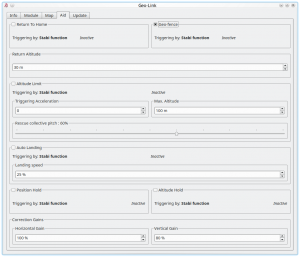
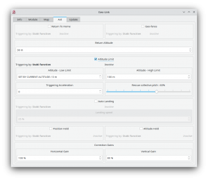
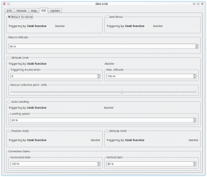
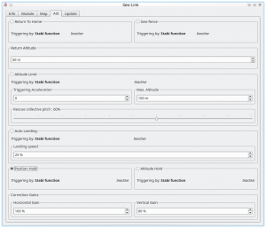
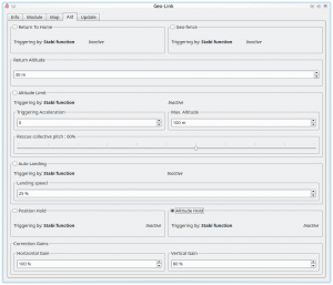
Check feature you would like to use in the Aid tab of the GeoLink window. After enabling, available parameters for the particular feature will be accessible. By these parameters behavior of selected feature can be customized to fulfill a needs. For the first tries we recommend to use a default values.
3.1 Triggering
You can verify if triggering mechanism is working correctly even before actual flight by checking the Aid tab. If a feature is engaged you will see ACTIVE or in other case Inactive.
For safety reasons do not engage any GeoLink feature before model is in the air at appropriate altitude.
3.1.1 Stabi function
By default all GeoLink features are engaged as soon as a Stabi function is active. For example if Coaxial or Rescue mode is engaged the GeoLink feature is engaged as well and complement operation of a Stabi function by acting simultaneously. We recommend to set Stabi/Function to Coaxial mode for Geo-fence, Return to Home and Position Hold features.
3.1.2 Dedicated GeoLink channel
Alternatively you can assign a GeoLink feature to any free channel in the General/Channels window. In the right part of the Spirit Settings software select which feature you would like to assign. (for example F: Return to Home). Then select appropriate channel which will be used for engaging. You can use same channel for multiple features at the same time.
4 Geo-fence
To enable this feature it is required to tick the CheckBox in the GeoLink window/Aid tab.
4.1 Usage
The feature can be engaged at any given time by a command from your radio. It is important to decide in which way the feature can be engaged as there are two options.
- To engage with Stabi function - in this case the feature is engaged when programmed Stabi function is engaged. This mean you do not need to assign any other switch than when used for e.g. Stabilisation mode
- To engage with assigned GeoLink channel - it is required to assign F: GeoLink Geo-fence function in the General/Channels to an available channel.
4.2 Modes
If Geo-fence is engaged by assigned GeoLink channel there is possibility to use tri-state switch also for programming of a new Geo-fence area. In the Channels window you will be able to see Function as On (1), Off and On (2) which is corresponding to 100%, 0% and -100% channel value.
When On (1) is displayed it mean that at this point Geo-fence is engaged and flight area is restricted. The model will return upon exceeding the area to the center of the area. Then pilot has to re-engage the feature in order to continue in flight.
When On (2) is displayed the unit is in a programming mode which allow to overwrite current Geo-fence to the new with position at which the model currently is. Please note that it will not work if model is flying or if GNSS signal is very weak.
4.3 New Geo-fence programming
It is possible to program the Geo-fence either with the Spirit Settings by selecting a points at the Map. Or there is possibility to use GeoLink channel to do so even if you are out of a computer.
If assigned GeoLink channel is used you have to set On (2) function state and keep it on for at least 2 seconds. At this period Status LED of the unit will turn off and after 2 seconds new Geo-fence point is programmed. Pilot has to define two points that will determine new area diagonally. To program both points pilot have to engage the programming two times. From two diagonal points a rectangular area is calculated. After the first point programming the Status LED at the Spirit will be still Off. After the second point programming the LED must turn On which will signalize success. New area is applied immediately.
5 Altitude Limit
To enable this feature it is required to tick the CheckBox in the GeoLink window/Aid tab.
5.1 Usage
The feature can be engaged at any given time by a command from your radio. It is important to decide in which way the feature can be engaged as there are two options.
- To engage with Stabi function - in this case the feature is engaged when programmed Stabi function is engaged. This mean you do not need to assign any other switch than when used for e.g. Stabilisation mode
- To engage with assigned GeoLink channel - it is required to assign F: GeoLink Altitude Limit function in the General/Channels to an available channel.
5.1.1 Triggering Acceleration
This parameter is key for engaging the Rescue mode fast enough if your model is approaching towards the ground. The faster is descending velocity, the faster the Rescue is engaged. This mean that the Rescue can be engaged above configured Minimum limit to save the model safely. If model is approaching the Minimum limit slowly then the rescue is engaged at configured level. Low Triggering Acceleration value is causing only minor difference.
6 Return to Home
To enable this feature it is required to tick the CheckBox in the GeoLink window/Aid tab.
6.1 Usage
The feature can be engaged at any given time by a command from your radio. It is important to decide in which way the feature can be engaged as there are two options.
- To engage with Stabi function - in this case the feature is engaged when programmed Stabi function is engaged. This mean you do not need to assign any other switch than when used for e.g. Stabilisation mode
- To engage with assigned GeoLink channel - it is required to assign F: GeoLink Return to Home function in the General/Channels to an available channel.
6.2 Modes
If Return to Home is engaged by assigned GeoLink channel there is possibility to use tri-state switch also for programming of a new Home spot. In the Channels window you will be able to see Function as On (1), Off and On (2) which is corresponding to 100%, 0% and -100% channel value.
When On (1) is displayed it mean that at this point Return to Home is engaged and model will move at the Home spot.
When On (2) is displayed the unit is in a programming mode which allow to overwrite current Home spot to the new with position at which the model currently is. Please note that it will not work if model is flying or if GNSS signal is very weak.
6.3 New Home position
It is possible to program the Home position either with the Spirit Settings by selecting a point at the Map. Or there is possibility to use GeoLink channel to do so even if you are out of a computer.
If assigned GeoLink channel is used you have to set On (2) function state and keep it on for at least 2 seconds. At this period Status LED of the unit will turn off and after 2 seconds new Home position is programmed. Once finished the LED must turn On again.
7 Position Hold
To enable this feature it is required to tick the CheckBox in the GeoLink window/Aid tab.
7.1 Usage
The feature can be engaged at any given time by a command from your radio. It is important to decide in which way the feature can be engaged as there are two options.
- To engage with Stabi function - in this case the feature is engaged when programmed Stabi function is engaged. This mean you do not need to assign any other switch than when used for e.g. Stabilisation mode
- To engage with assigned GeoLink channel - it is required to assign F: GeoLink Position Hold function in the General/Channels to an available channel.
8 Altitude Hold
To enable this feature it is required to tick the CheckBox in the GeoLink window/Aid tab.
8.1 Usage
The feature can be engaged at any given time by a command from your radio. It is important to decide in which way the feature can be engaged as there are two options.
- To engage with Stabi function - in this case the feature is engaged when programmed Stabi function is engaged. This mean you do not need to assign any other switch than when used for e.g. Stabilisation mode
- To engage with assigned GeoLink channel - it is required to assign F: GeoLink Altitude Hold function in the General/Channels to an available channel.
8.2 Modes
If Altitude Hold is engaged by assigned GeoLink channel there is possibility to use tri-state switch also for disabling Collective Pitch input. In the Channels window you will be able to see Function as On (1), Off and On (2) which is corresponding to 100%, 0% and -100% channel value.
When On (1) is displayed it mean that altitude in which the feature was engaged will be held. Pilot is still able to change Collective Pitch, but in a limited manner. Collective Pitch reaction will be slower than in a normal flight mode.
When On (2) is displayed it mean that altitude in which the feature was engaged will be held. Pilot is unable to change Collective Pitch by pitch stick. So that Collective Pitch steering is fixed and is changed only by GeoLink in order to hold right altitude.
9 Correction Gains
GeoLink features are doing a certain movements to achieve desired position of the model. These movements are small corrections which are dependent on parameters of the model. For very agile models these correction can be smaller. While for heavy and big models you might need bigger in order to reduce time required to achieve desired position.
9.1 Horiontal Gain
Horizontal gain affects features such as Geo-fence, Return To Home and Position Hold. For example if Return to Home feature is engaged and it takes too long to return at programmed home spot it is necessary to increase Horizontal correction. Too high value will result in excess (too visible) corrections even when model is maintaining spot on position.
9.2 Vertical Gain
Vertical gain affects features such as Altitude Limit and Altitude Hold.

