Difference between revisions of "GeoLink Configuration/it"
(Created page with "Quando viene visualizzato '''On (1)''' significa che a questo punto Geo-fence è impegnato e l'area di volo è limitata. Il modello tornerà dal superamento dell'area al centr...") |
|||
| Line 97: | Line 97: | ||
Nella finestra Canali potrai vedere Funzione come '''On (1)''', '''Off''' e '''On (2)''' che corrisponde a 100%, 0% e -100% del valore del canale. | Nella finestra Canali potrai vedere Funzione come '''On (1)''', '''Off''' e '''On (2)''' che corrisponde a 100%, 0% e -100% del valore del canale. | ||
| − | Quando viene visualizzato '''On (1)''' significa che a questo punto Geo-fence è impegnato e l'area di volo è limitata. Il modello tornerà dal superamento dell'area al centro dell'area. Quindi il pilota deve | + | Quando viene visualizzato '''On (1)''' significa che a questo punto Geo-fence è impegnato e l'area di volo è limitata. Il modello tornerà dal superamento dell'area al centro dell'area. Quindi il pilota deve impegnarsi nuovamente per continuare il volo. |
When '''On (2)''' is displayed the unit is in a programming mode which allow to overwrite current Geo-fence to the new with position at which the model currently is. Please note that it will not work if model is flying or if GNSS signal is very weak. | When '''On (2)''' is displayed the unit is in a programming mode which allow to overwrite current Geo-fence to the new with position at which the model currently is. Please note that it will not work if model is flying or if GNSS signal is very weak. | ||
Revision as of 18:43, 15 January 2021
Contents
1 Supporto GeoLink
GeoLink è supportato dalla versione firmware 2.5. Per utilizzare tutte le funzioni è necessario abilitare il supporto nelle Impostazioni Spirito - prima scheda Generale General tab. Dopo l'abilitazione, salvare le impostazioni e alimentare nuovamente il modello.
2 Calibrazione della bussola
Tutti i moduli GeoLink sono stati completamente testati e calibrati. L'unica cosa di cui il pilota potrebbe aver bisogno è ricalibrare la bussola. La bussola è fondamentale per determinare la direzione del modello per una corretta navigazione nello spazio. La bussola rileva il campo magnetico terrestre (campo geomagnetico) e in questo modo può determinare la direzione in qualsiasi momento. Purtroppo il campo geomagnetico è diverso ovunque. Pertanto se il modello verrà utilizzato al di fuori della Repubblica Ceca, si consiglia vivamente di eseguire una nuova calibrazione. I moduli GeoLink sono calibrati in fabbrica per la Repubblica Ceca.
2.1 Come controllare
Per verificare che GeoLink sia calibrato correttamente per la tua area, avvia le Spirit Settings e apri la finestra GeoLink settings. Nella scheda Informazioni Info tab puoi vedere il valore corrente dell'intestazione.
Posizionare il modello o solo GeoLink al Nord il più vicino possibile, in modo che la direzione di volo del modello sia davanti alla freccia. Idealmente confronta con una bussola analogica.
IMPORTANTE: Assicurarsi che durante la lettura del titolo, il modello sia sul piano orizzontale. In modo che nella scheda Modulo Module tab vedrai un'inclinazione di 0 °. Poiché alcuni modelli come SAB Goblin, MSH Protos sono inclinati, è necessario prima trovare l'inclinazione zero del modello.
Quando ci si dirige verso Nord, si dovrebbero vedere circa 90 +/- 4 ° . Il valore misurato non dovrebbe essere lontano da questo.
Si consiglia di non utilizzare dispositivi intelligenti per il confronto della direzione della bussola. Questi di solito non sono calibrati affatto né consentono la calibrazione. Una bussola analogica è la migliore per il confronto.
2.2 Comportamento strano
Se la calibrazione della bussola è sbagliata, noterai che funzioni come Geo-fence, Return to Home, Position Hold non funzionano esattamente. Ad esempio, quando Return to Home è attivato e il modello ha raggiunto la posizione Home programmata, il modello potrebbe muoversi in modo circolare attorno a quel punto, invece di rimanere stabile. Più grande è il cerchio, maggiore è l'errore di direzione della bussola. Se riesci a osservare sempre questo comportamento, allora è un chiaro segno che devi ricalibrare la bussola.
2.3 Processo di calibrazione
Per eseguire la calibrazione è necessario entrare in Impostazioni Spirito / GeoLink / Modulo e fare clic sul pulsante Calibration request. Ora puoi scollegare l'alimentazione e il cavo di interfaccia USB dal modello.
- Alla successiva accensione del modello si noteranno immediatamente 3 serie di lampeggi rapidi del LED sul GeoLink.
- Il LED di stato indicherà quindi l'avanzamento della calibrazione. Inizia a muoverti con il modello in tutte le direzioni e angoli possibili per imitare una sfera. Qualsiasi lampeggio del LED indicherà che sono stati acquisiti nuovi dati di calibrazione.
- Ruota con il modulo finché non vedrai lampeggiare periodicamente il LED. A questo punto la calibrazione è terminata. Dopo la successiva alimentazione, il modulo è pronto per il funzionamento.
Per gli elicotteri di classe 600 e piu grandi si consiglia di eseguire la calibrazione mentre GeoLink non è montato. In questo modo può essere più comodo e più facile.
La calibrazione dovrebbe essere eseguita idealmente sul campo di volo, ma di solito può essere eseguita anche al coperto se il segnale e' buono.
Calibration will not finish until it is fully done. If power is turned off while calibration is not finished, the calibration process will start from the beginning on next power up.
3 Come configurare
Come primo passo, il pilota deve decidere quale funzione GeoLink desidera utilizzare. Per scoprire come funziona ciascuna funzionalità, visita la Pagina delle caratteristiche. Il pilota può abilitare più funzionalità contemporaneamente, se necessario.
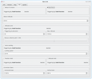
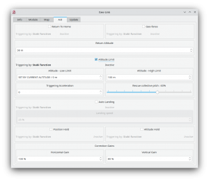
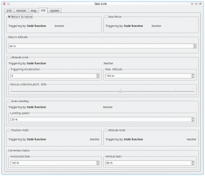
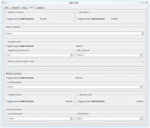
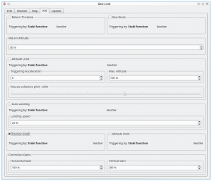
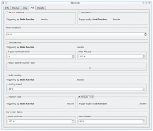
Seleziona la funzione che desideri utilizzare nella scheda Aiuto della finestra GeoLink. Dopo l'abilitazione, saranno accessibili i parametri disponibili per la particolare funzione. Con questi parametri il comportamento della caratteristica selezionata può essere personalizzato per soddisfare le esigenze. Per i primi tentativi si consiglia di utilizzare valori predefiniti.
3.1 Attivazione
Puoi verificare se il meccanismo di attivazione funziona correttamente anche prima del volo effettivo controllando la scheda Aiuto. Se una funzione è attiva, vedrai ACTIVE o in altri casi INACTIVE.
IMPORTANTE Per motivi di sicurezza, non attivare alcuna funzione GeoLink prima che il modello sia in aria ad un'altitudine appropriata.
3.1.1 Funzione Stabi
Per impostazione predefinita, tutte le funzionalità di GeoLink vengono attivate non appena una funzione Stabi è attiva. Ad esempio, se è attiva la modalità Coassiale o Rescue, viene attivata anche la funzione GeoLink e completa il funzionamento di una funzione Stabi agendo contemporaneamente. Si consiglia di impostare Stabi / Function in modalità Coassiale per le funzioni Geo-fence, Return to Home e Position Hold.
3.1.2 Canale GeoLink dedicato
In alternativa puoi assegnare una funzione GeoLink a qualsiasi canale libero nella finestra Generale / Canali. Nella parte destra del software Spirit Settings seleziona la funzione che desideri assegnare. (ad esempio F: Return to Home). Quindi seleziona il canale appropriato che verrà utilizzato per la funzione desiderata. Puoi utilizzare lo stesso canale per più funzioni contemporaneamente.
4 Geo-fence
Per abilitare questa funzione è necessario spuntare la casella di controllo nella finestra GeoLink / scheda Aiuto.
4.1 Utilizzo
La funzione può essere attivata in qualsiasi momento tramite un comando dalla radio. È importante decidere in che modo la funzione può essere attivata poiché ci sono due opzioni.
- Per impegnarsi con la funzione Stabi - in questo caso la funzione è attiva quando è attivata la funzione Stabi programmata. Ciò significa che non è necessario assegnare alcun interruttore diverso da quando viene utilizzato ad es. Modalità di stabilizzazione
- Per entrare in contatto con il canale GeoLink assegnato - è necessario assegnare la funzione F: GeoLink Geo-fence in Generale / Canali a un canale disponibile.
4.2 Modalità
Se Geo-fence è impegnato dal canale GeoLink assegnato c'è la possibilità di utilizzare lo switch a tre posizioni anche per la programmazione di una nuova area Geo-fence. Nella finestra Canali potrai vedere Funzione come On (1), Off e On (2) che corrisponde a 100%, 0% e -100% del valore del canale.
Quando viene visualizzato On (1) significa che a questo punto Geo-fence è impegnato e l'area di volo è limitata. Il modello tornerà dal superamento dell'area al centro dell'area. Quindi il pilota deve impegnarsi nuovamente per continuare il volo.
When On (2) is displayed the unit is in a programming mode which allow to overwrite current Geo-fence to the new with position at which the model currently is. Please note that it will not work if model is flying or if GNSS signal is very weak.
4.3 New Geo-fence programming
It is possible to program the Geo-fence either with the Spirit Settings by selecting a points at the Map. Or there is possibility to use GeoLink channel to do so even if you are out of a computer.
If assigned GeoLink channel is used you have to set On (2) function state and keep it on for at least 2 seconds. At this period Status LED of the unit will turn off and after 2 seconds new Geo-fence point is programmed. Pilot has to define two points that will determine new area diagonally. To program both points pilot have to engage the programming two times. From two diagonal points a rectangular area is calculated. After the first point programming the Status LED at the Spirit will be still Off. After the second point programming the LED must turn On which will signalize success. New area is applied immediately.
5 Altitude Limit
To enable this feature it is required to tick the CheckBox in the GeoLink window/Aid tab.
5.1 Usage
The feature can be engaged at any given time by a command from your radio. It is important to decide in which way the feature can be engaged as there are two options.
- To engage with Stabi function - in this case the feature is engaged when programmed Stabi function is engaged. This mean you do not need to assign any other switch than when used for e.g. Stabilisation mode
- To engage with assigned GeoLink channel - it is required to assign F: GeoLink Altitude Limit function in the General/Channels to an available channel.
5.1.1 Triggering Acceleration
This parameter is key for engaging the Rescue mode fast enough if your model is approaching towards the ground. The faster is descending velocity, the faster the Rescue is engaged. This mean that the Rescue can be engaged above configured Minimum limit to save the model safely. If model is approaching the Minimum limit slowly then the rescue is engaged at configured level. Low Triggering Acceleration value is causing only minor difference.
6 Return to Home
To enable this feature it is required to tick the CheckBox in the GeoLink window/Aid tab.
6.1 Usage
The feature can be engaged at any given time by a command from your radio. It is important to decide in which way the feature can be engaged as there are two options.
- To engage with Stabi function - in this case the feature is engaged when programmed Stabi function is engaged. This mean you do not need to assign any other switch than when used for e.g. Stabilisation mode
- To engage with assigned GeoLink channel - it is required to assign F: GeoLink Return to Home function in the General/Channels to an available channel.
6.2 Modes
If Return to Home is engaged by assigned GeoLink channel there is possibility to use tri-state switch also for programming of a new Home spot. In the Channels window you will be able to see Function as On (1), Off and On (2) which is corresponding to 100%, 0% and -100% channel value.
When On (1) is displayed it mean that at this point Return to Home is engaged and model will move at the Home spot.
When On (2) is displayed the unit is in a programming mode which allow to overwrite current Home spot to the new with position at which the model currently is. Please note that it will not work if model is flying or if GNSS signal is very weak.
6.3 New Home position
It is possible to program the Home position either with the Spirit Settings by selecting a point at the Map. Or there is possibility to use GeoLink channel to do so even if you are out of a computer.
If assigned GeoLink channel is used you have to set On (2) function state and keep it on for at least 2 seconds. At this period Status LED of the unit will turn off and after 2 seconds new Home position is programmed. Once finished the LED must turn On again.
7 Auto Landing
To enable this feature it is required to tick the CheckBox in the GeoLink window/Aid tab.
7.1 Usage
The feature can be engaged at any given time by a command from your radio. It is important to decide in which way the feature can be engaged as there are two options.
- To engage with Stabi function - in this case the feature is engaged when programmed Stabi function is engaged. This mean you do not need to assign any other switch than when used for e.g. Stabilisation mode
- To engage with assigned GeoLink channel - it is required to assign F: GeoLink Auto Landing function in the General/Channels to an available channel.
8 Position Hold
To enable this feature it is required to tick the CheckBox in the GeoLink window/Aid tab.
8.1 Usage
The feature can be engaged at any given time by a command from your radio. It is important to decide in which way the feature can be engaged as there are two options.
- To engage with Stabi function - in this case the feature is engaged when programmed Stabi function is engaged. This mean you do not need to assign any other switch than when used for e.g. Stabilisation mode
- To engage with assigned GeoLink channel - it is required to assign F: GeoLink Position Hold function in the General/Channels to an available channel.
9 Altitude Hold
To enable this feature it is required to tick the CheckBox in the GeoLink window/Aid tab.
9.1 Usage
The feature can be engaged at any given time by a command from your radio. It is important to decide in which way the feature can be engaged as there are two options.
- To engage with Stabi function - in this case the feature is engaged when programmed Stabi function is engaged. This mean you do not need to assign any other switch than when used for e.g. Stabilisation mode
- To engage with assigned GeoLink channel - it is required to assign F: GeoLink Altitude Hold function in the General/Channels to an available channel.
9.2 Modes
If Altitude Hold is engaged by assigned GeoLink channel there is possibility to use tri-state switch also for disabling Collective Pitch input. In the Channels window you will be able to see Function as On (1), Off and On (2) which is corresponding to 100%, 0% and -100% channel value.
When On (1) is displayed it mean that altitude in which the feature was engaged will be held. Pilot is still able to change Collective Pitch, but in a limited manner. Collective Pitch reaction will be slower than in a normal flight mode.
When On (2) is displayed it mean that altitude in which the feature was engaged will be held. Pilot is unable to change Collective Pitch by pitch stick. So that Collective Pitch steering is fixed and is changed only by GeoLink in order to hold right altitude.
10 Correction Gains
GeoLink features are doing a certain movements to achieve desired position of the model. These movements are small corrections which are dependent on parameters of the model. For very agile models these correction can be smaller. While for heavy and big models you might need bigger in order to reduce time required to achieve desired position.
10.1 Horiontal Gain
Horizontal gain affects features such as Geo-fence, Return To Home and Position Hold. For example if Return to Home feature is engaged and it takes too long to return at programmed home spot it is necessary to increase Horizontal correction. Too high value will result in excess (too visible) corrections even when model is maintaining spot on position.
10.2 Vertical Gain
Vertical gain affects features such as Altitude Limit and Altitude Hold.

