Difference between revisions of "CrossFire CRSF"
| (8 intermediate revisions by the same user not shown) | |||
| Line 7: | Line 7: | ||
</translate> | </translate> | ||
| − | [[File:CRSF-Wiring.jpg| | + | [[File:CRSF-Wiring.jpg|400px]] |
== <translate>Wiring</translate> == | == <translate>Wiring</translate> == | ||
| − | + | === CrossFire TBS === | |
[[File:CRSF-Wiring2.jpg|500px]] [[File:CRSF-Wiring3.jpg|500px]] | [[File:CRSF-Wiring2.jpg|500px]] [[File:CRSF-Wiring3.jpg|500px]] | ||
| − | '''RUD port''' - direct cable between CRSF RX Ch. Out 1 | + | '''RUD port''' - direct cable between '''CRSF RX Ch. Out 1''' |
| − | '''AIL pin''' (pin closer to the port label) - wire to CRSF RX Ch. Out 2 signal pin | + | '''AIL pin''' (pin closer to the port label) - wire to '''CRSF RX Ch. Out 2''' signal pin |
| + | |||
| + | === RadioMaster ELRS === | ||
| + | |||
| + | [[File:CRSF-Wiring4.jpg|500px]] | ||
| + | |||
| + | '''RUD port''' - black '''-''', red '''+''' powering wires, white '''TX''' signal. | ||
| + | |||
| + | '''AIL pin''' (pin closer to the port label) - green '''RX''' signal pin. | ||
== <translate><!--T:24--> | == <translate><!--T:24--> | ||
| Line 26: | Line 34: | ||
Then save the settings (e.g. by ''CTRL+S'') or the ''Backup tab/Unit - Save'' and restart the unit.</translate> | Then save the settings (e.g. by ''CTRL+S'') or the ''Backup tab/Unit - Save'' and restart the unit.</translate> | ||
| − | [[File:CRSF-settings.png| | + | [[File:CRSF-settings.png|450px|center]] |
== <translate><!--T:85--> | == <translate><!--T:85--> | ||
| Line 39: | Line 47: | ||
<translate>Integration support is to be added within following updates.</translate> | <translate>Integration support is to be added within following updates.</translate> | ||
| + | |||
| + | == RadioMaster CRSF Settings == | ||
| + | |||
| + | In order to make RM receivers working well we recommend following settings. These settings can be adjusted at the CROSSFIRE SETUP menu. | ||
| + | |||
| + | === RM Ranger === | ||
| + | * Packet Rate: '''100Hz Full''' | ||
| + | * Telem Ratio: '''1:2''' | ||
| + | * Switch Mode: '''8Ch''' | ||
| + | |||
| + | === RM RPH-3 === | ||
| + | * Init Rate: '''F1000''' | ||
| + | |||
| + | === Spirit Settings === | ||
| + | |||
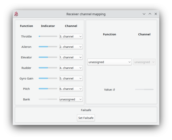
| + | ELRS connection require to change Channel Mapping from default. | ||
| + | |||
| + | Elevator should be set to '''Channel 1'''. | ||
| + | Throttle to '''Channel 3'''. | ||
| + | |||
| + | [[File:ELRS-Mapping.png|600px]] | ||
Latest revision as of 14:24, 5 December 2024
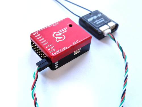
CrossFire CRSF is protocol designed by Team Blacksheep (TBS) which is supported by all Spirit units except Spirit 1 and micro Spirit. It is for sending all channel data and telemetry at the same time. This mean that you do not have to connect anything else except 4 wires.
There are multiple receivers and satellites with CrossFire CRSF support.
Both cable ends can look like this:
Contents
1 Wiring
1.1 CrossFire TBS
RUD port - direct cable between CRSF RX Ch. Out 1
AIL pin (pin closer to the port label) - wire to CRSF RX Ch. Out 2 signal pin
1.2 RadioMaster ELRS
RUD port - black -, red + powering wires, white TX signal.
AIL pin (pin closer to the port label) - green RX signal pin.
2 Spirit Settings
Now you are ready to power up the unit. If your Power supply is not connected yet, we recommend to connect it to the AUX1, AUX2 and/or CH0 port. Before you can utilize the CrossFire connection, it is important to set the CrossFire CRSF receiver type in the General tab of the software. Please start the Spirit Settings and change the receiver type as displayed on the photo. Then save the settings (e.g. by CTRL+S) or the Backup tab/Unit - Save and restart the unit.
3 Throttle output
You can connect ESC or Throttle servo directly to the Spirit unit at (AUX/AUX1 port).
4 Radio Integration
Integration support is to be added within following updates.
5 RadioMaster CRSF Settings
In order to make RM receivers working well we recommend following settings. These settings can be adjusted at the CROSSFIRE SETUP menu.
5.1 RM Ranger
- Packet Rate: 100Hz Full
- Telem Ratio: 1:2
- Switch Mode: 8Ch
5.2 RM RPH-3
- Init Rate: F1000
5.3 Spirit Settings
ELRS connection require to change Channel Mapping from default.
Elevator should be set to Channel 1. Throttle to Channel 3.


