Difference between revisions of "GeoLink Geofence"
(Marked this version for translation) |
|||
| (One intermediate revision by the same user not shown) | |||
| Line 1: | Line 1: | ||
| + | <languages /> | ||
| + | |||
| + | |||
== <translate><!--T:28--> | == <translate><!--T:28--> | ||
Geo-fence</translate> == | Geo-fence</translate> == | ||
| − | === <translate>How it works</translate> === | + | === <translate><!--T:87--> |
| + | How it works</translate> === | ||
| − | <translate>When model fly over configured fence it will try to stop and return back to allowed area as fast as possible. | + | <translate><!--T:88--> |
| + | When model fly over configured fence it will try to stop and return back to allowed area as fast as possible. | ||
This feature can work also upside down in the same way. | This feature can work also upside down in the same way. | ||
Rudder control is identical as with a normal flying mode.</translate> | Rudder control is identical as with a normal flying mode.</translate> | ||
| − | <translate>To enable this feature it is required to tick the CheckBox in the GeoLink window/Aid tab.</translate> | + | <translate><!--T:89--> |
| + | To enable this feature it is required to tick the CheckBox in the GeoLink window/Aid tab.</translate> | ||
[[File:geolink-geofence.png|center|thumb]] | [[File:geolink-geofence.png|center|thumb]] | ||
| Line 33: | Line 39: | ||
In the Channels window you will be able to see Function as '''On (1)''', '''Off''' and '''On (2)''' which is corresponding to 100%, 0% and -100% channel value. | In the Channels window you will be able to see Function as '''On (1)''', '''Off''' and '''On (2)''' which is corresponding to 100%, 0% and -100% channel value. | ||
| − | ==== On (1) ==== | + | ==== On (1) ==== <!--T:90--> |
<!--T:82--> | <!--T:82--> | ||
When '''On (1)''' is displayed it mean that at this point Geo-fence is engaged and flight area is restricted. The model will return upon exceeding the area to the center of the area. Then pilot have to touch the aileron or elevator stick in order to continue in flight. | When '''On (1)''' is displayed it mean that at this point Geo-fence is engaged and flight area is restricted. The model will return upon exceeding the area to the center of the area. Then pilot have to touch the aileron or elevator stick in order to continue in flight. | ||
| − | ==== On (2) ==== | + | ==== On (2) ==== <!--T:83--> |
| − | <!--T:83--> | + | |
When '''On (2)''' is displayed the unit is in a programming mode which allow to overwrite current Geo-fence to the new with position at which the model currently is. Please note that it will not work if model is flying or if GNSS signal is very weak.</translate> | When '''On (2)''' is displayed the unit is in a programming mode which allow to overwrite current Geo-fence to the new with position at which the model currently is. Please note that it will not work if model is flying or if GNSS signal is very weak.</translate> | ||
| Line 56: | Line 61: | ||
=== Programming at computer === | === Programming at computer === | ||
| − | <translate>The easiest is to program Geo-fence area directly from your computer. By selecting points at the Map you can set the fence.</translate> | + | <translate><!--T:91--> |
| + | The easiest is to program Geo-fence area directly from your computer. By selecting points at the Map you can set the fence.</translate> | ||
<translate> | <translate> | ||
| + | <!--T:92--> | ||
#Go the Map Tab and there click at the '''Set button''' in Geo-fence subwindow. Please note the feature must be enabled in the Aid Tab first. | #Go the Map Tab and there click at the '''Set button''' in Geo-fence subwindow. Please note the feature must be enabled in the Aid Tab first. | ||
#Select 4 points at the map to program area in which the model is allowed to fly | #Select 4 points at the map to program area in which the model is allowed to fly | ||
| Line 65: | Line 72: | ||
[[File:geolink-geofence-set.png|600px]] | [[File:geolink-geofence-set.png|600px]] | ||
| − | === <translate>Return Altitude</translate> === | + | === <translate><!--T:93--> |
| + | Return Altitude</translate> === | ||
| − | <translate>If you will set '''Return Altitude''' parameter to a non-zero value then model will automatically reach and maintain this altitude when the function is engaged. If you want to control collective pitch when this function is enabled it is enough to set 0 for this parameter.</translate> | + | <translate><!--T:94--> |
| + | If you will set '''Return Altitude''' parameter to a non-zero value then model will automatically reach and maintain this altitude when the function is engaged. If you want to control collective pitch when this function is enabled it is enough to set 0 for this parameter.</translate> | ||
| Line 74: | Line 83: | ||
{|style="width: 100%;color: white;" | {|style="width: 100%;color: white;" | ||
|- | |- | ||
| − | | style="width: 33%;"| [[<translate>GeoLink_Configuration</translate>|← <translate>Configuration</translate>]] | + | | style="width: 33%;"| [[<translate><!--T:95--> |
| + | GeoLink_Configuration</translate>|← <translate><!--T:96--> | ||
| + | Configuration</translate>]] | ||
| style="width: 33%;text-align:center;"| [[#up|↑<translate><!--T:74--> | | style="width: 33%;text-align:center;"| [[#up|↑<translate><!--T:74--> | ||
Up</translate>↑]] | Up</translate>↑]] | ||
Latest revision as of 14:40, 15 September 2022
Contents
1 Geo-fence
1.1 How it works
When model fly over configured fence it will try to stop and return back to allowed area as fast as possible. This feature can work also upside down in the same way. Rudder control is identical as with a normal flying mode.
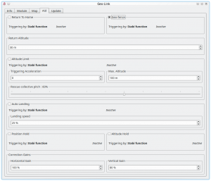
To enable this feature it is required to tick the CheckBox in the GeoLink window/Aid tab.
1.2 Usage
The feature can be engaged at any given time by a switch of your radio. It is important to decide in which way the feature will be engaged as there are two options:
- To engage with Stabi function - in this case the feature is engaged when programmed Stabi function is engaged. This mean you do not need to assign any other switch than when used for e.g. Stabilisation mode
- To engage with assigned GeoLink channel - it is required to assign F: GeoLink Geo-fence function in the General/Channels to an available channel.
Please make sure that Geo-fence Area was defined. Four points must be programmed. The Spirit Settings will display right order to program all points.
1.3 Modes
If Geo-fence is engaged by assigned GeoLink channel there is possibility to use tri-state switch also for programming of a new Geo-fence area. In the Channels window you will be able to see Function as On (1), Off and On (2) which is corresponding to 100%, 0% and -100% channel value.
1.3.1 On (1)
When On (1) is displayed it mean that at this point Geo-fence is engaged and flight area is restricted. The model will return upon exceeding the area to the center of the area. Then pilot have to touch the aileron or elevator stick in order to continue in flight.
1.3.2 On (2)
When On (2) is displayed the unit is in a programming mode which allow to overwrite current Geo-fence to the new with position at which the model currently is. Please note that it will not work if model is flying or if GNSS signal is very weak.
1.4 Programming at field
It is possible to program the Geo-fence either with the Spirit Settings by selecting 4 points at the Map. Or there is possibility to use GeoLink channel to do so even if you are out of a computer.
If assigned GeoLink channel is used you have to set On (2) function state and keep it on for at least 2 seconds. At this period Status LED of the Spirit unit will turn off and after 2 seconds new Geo-fence point is programmed. Pilot has to define four points that will determine new area. To program all four points pilot have to engage the programming four times. Only once all points are programmed the Status LED of the Spirit unit will turn On which will signalize success. New area is applied immediately.
1.5 Programming at computer
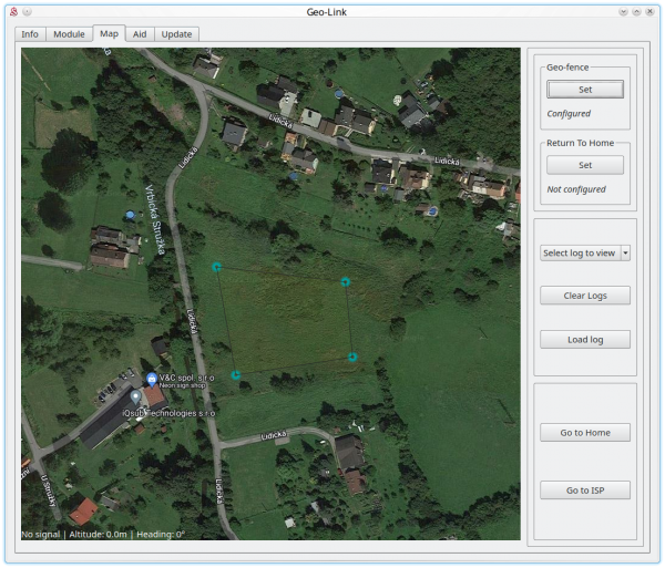
The easiest is to program Geo-fence area directly from your computer. By selecting points at the Map you can set the fence.
- Go the Map Tab and there click at the Set button in Geo-fence subwindow. Please note the feature must be enabled in the Aid Tab first.
- Select 4 points at the map to program area in which the model is allowed to fly
- If needed you can set new area by clicking the Set button again.
1.6 Return Altitude
If you will set Return Altitude parameter to a non-zero value then model will automatically reach and maintain this altitude when the function is engaged. If you want to control collective pitch when this function is enabled it is enough to set 0 for this parameter.

