Difference between revisions of "GeoLink Mounting"
| Line 23: | Line 23: | ||
| − | [[File:geolink-horizontal.jpg|400px| | + | [[File:geolink-horizontal.jpg|400px|center]] |
| − | '' | + | <center>''Example:'' Position is '''Horizontal (0°)'''; Rotor head is at the left side.</center> |
| + | |||
| + | <br/> | ||
| + | {{Info|[[File:info.png]] Each circuit containing antennas is very carefully designed to achieve correct impedance. Impedance is changing immediately by placing any parts close to the circuit, especially near antenna. Because PCB is acting as a part of GPS antenna any change to the PCB, including screws has noticeable impact.}} | ||
| + | |||
| + | == Wiring == | ||
| + | |||
| + | Wiring is done through one JST to JST cable with length of 22cm which is supplied with GeoLink. Longer cable is possible and will be available. | ||
| + | For GPS itself a shorter cable is better, because any additional cables attached to the module and even unit could distort the signal. | ||
| + | |||
| + | {{Info|[[File:info.png]] GeoLink cable is compatible with Spektrum satellite cables.}} | ||
| + | |||
| + | |||
| + | == Alignment == | ||
| + | |||
| + | Since it is uneasy to visually align the module perfectly, the GeoLink has built-in digital level in the Spirit Settings. There you can see how to align the module and perform a necessary adjustments. | ||
| + | |||
| + | [[File:GeoLink-Alignment.png|halfwidth|center]] | ||
Revision as of 10:23, 28 May 2018
Correct mounting is the most important for achieving optimal operating condition. If done improperly GeoLink will be unable to work with great precision or in the worst case some functionality could be even not usable.
Please take special care in order to perform the following steps thoroughly.
1 Mounting on your helicopter
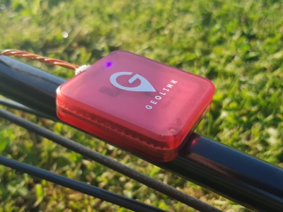
As of now, module must be mounted always horizontally so that GeoLink logo is at the top. You can select from two positions:
- Horizontal (0°) - connector is pointing to main rotor
- Horizontal (180°) - connector is pointing to tail rotor
GeoLink module should be mounted ideally at the TAIL BOOM. This is usually the best position for achieving optimal performance. Optimal position should meet the following:
- It is at least 5cm far from a rigid conductive parts such as carbon frame
- It is at least 5cm far from any electronics (especially servos)
- It is at least 8cm far from an electric motor
- It has clear sky visibility
- It is perfectly horizontally aligned
Module attachment is normally performed by provided Double Sided tape. Provided tape has extremely good bonding properties so that it can hold more than better even when only two rails of the tape is used.
Some helicopters are equipped with fuselages instead of a boom. In that case there is chance you will have to spend time to achieve flat mounting surface.
Each circuit containing antennas is very carefully designed to achieve correct impedance. Impedance is changing immediately by placing any parts close to the circuit, especially near antenna. Because PCB is acting as a part of GPS antenna any change to the PCB, including screws has noticeable impact.
2 Wiring
Wiring is done through one JST to JST cable with length of 22cm which is supplied with GeoLink. Longer cable is possible and will be available. For GPS itself a shorter cable is better, because any additional cables attached to the module and even unit could distort the signal.
3 Alignment
Since it is uneasy to visually align the module perfectly, the GeoLink has built-in digital level in the Spirit Settings. There you can see how to align the module and perform a necessary adjustments.

