Configuration
Le logiciel offre un assistant de configuration. Il est très recommandé d'utiliser cet assistant parce qu'il vous guidera tout au long de la configuration depuis le debut jusqu'au premier vol.
Contents
1 CONNECTION A UN PC
Avant de commencer la configuration il est nécessaire de connecter le module à l'ordinateur via le port USB. En fonction du système d'exploitation et de l'ordinateur, il peut être nécessaire d'installer un pilote de périphérique (driver) après la connexion du câble sur le port USB.
Le logiciel Spirit Settings est disponible pour les systèmes d'exploitation suivants:
- Microsoft Windows
- Apple OS X
- GNU/Linux
- FreeBSD
Une fois connecté et le pilote de périphérique installé avec succès, un nouveau port COM virtual devrait être visible dans le logiciel et dans le gestionnaire de périphérique.
MICROSOFT WINDOWS
Installez le pilote de périphérique en utilisant l'installateur logiciel. La procédure est décrite dans la section suivante.
APPLE MAC OS X
Pour un bon fonctionnement il est important de télécharger et installer le pilote de périphérique venant de l'adresse URL suivante:
http://spirit-system.com/dl/driver/SiLabsUSBDriverDisk.dmg
GNU/LINUX a FreeBSD
Aucune installation est nécessaire.
1.1 WIFI-LINK
Le logiciel Spirit Settings peut maintenant se connecter avec le module Wifi. Il s'appelle "Spirit Wifi-Link". Le Wifi-Link peut complètement remplacer l'interface USB. Ainsi, l'utilisateur peut effectuer sa configuration sans fil. Vous trouverez la description de la connexion et toutes les instructions dans le Guide Wifi-Link.
2 CONNEXION AU MODULE
Après avoir connecté l'interface USB à votre ordinateur, connectez le câble d'interface sur le port SYS du module Spirit FBL. Le module Spirit FBL ne peut pas être alimenté par le câble USB sur le port SYS, il est donc nécessaire de l'alimenter depuis un récepteur, un BEC ou une batterie externe. Les port RUD et AUX permettent d'alimenter le module Spirit FBL et si vous utilisez un BEC ou une batterie, veillez à avoir une tension comprise entre 3V et 15V. Le fil du milieu doit être le positif.
Ne branchez jamais un connecteur d'alimentation sur les port SYS ou ELE/PIT/AIL du module.
NOTE
Si le module n'est pas encore configuré (e.g. un nouveau module) il est conseillé de ne connecter aucun servo à ce stade.
3 INSTALLATION DU LOGICIEL DE CONFIGURATION
Ci-dessous les instructions pour les plateformes supportées. Le logiciel de configuration est disponible sur le site Web Spirit System:spirit-system.com/.
MICROSOFT WINDOWS
Lancez l'installateur et suivez l'assistant.
Si le pilote de périphérique n'est pas encore installé, une option vous le proposera lors de l'installation.
L'installateur va parcourir les étapes nécessaires à la préparation de votre ordinateur pour utiliser le logiciel de configuration. A la fin de l'installation, le logiciel de configuration appelé "Spirit Settings" pourra être lancé depuis le Bureau ou la liste de programmes.
APPLE MAC OS X
Lancez l'installation du logiciel téléchargé en ouvrant le fichier DMG puis en déplaçant le contenu dans le répertoire Applications. Le logiciel de configuration "Spirit Settings" peut alors être lancé depuis le répertoire Applications.
GNU/LINUX a FreeBSD
Extrayez les fichier depuis l'archive téléchargée, par example dans votre répertoire utilisateur.
Le logiciel de configuration peut être lancé depuis le répertoire qui vient d'être créé avec le fichier "settings.sh"
4 LOGICIEL DE CONFIGURATION
Une fois le logiciel installé, assurez-vous que le module Spirit connecté via l'USB au port SYS est alimenté et initialisé (la LED verte est allumée). Puis, lancez le logiciel sur votre ordinateur.
Lancez le logiciel Spirit Settings depuis votre bureau ou depuis répertoire dans lequel il a été installé.
NOTE
Le logiciel de configuration doit être lancé après que le module a été initialisé. A chaque fois que le Spirit FBL est initialisé (la LED de status est active) et connecté, vous pouvez modifier les paramètres.
La configuration pendant le vol n'est pas possible à cause des risques de sécurité que cela implique.
PROBLEMES AVEC WINDOWS
Si le logiciel de configuration ne peut trouver un port COM valide, vous pouvez lancer le logiciel en mode Administrateur.
D'autre part, vérifiez le numéro de port COM. Si la valeur est trop élevée, essayez de changer le numéro de port (Silabs Device) en COM1-COM4 par exemple.
Sur les laptops il peut être nécessaire de désactiver les fonctions d'économie d'énergie dans le Gestionnaire de périphériques.
5 UTILISATION DU LOGICIEL
Après une bonne connexion du module Spirit FBL, toutes les fonctions de configuration devraient être disponibles. Si ce n'est pas le cas, essayez soit de choisir un autre port COM (Périphérique) ou essayez de relancer le logiciel, en débranchant le module de l'alimentation et en répétant la procédure.
Attendez que le module soit initialisé avant de lancer le logiciel.
5.1 ONGLET CONNEXION
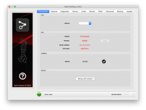
Cet onglet indique l'état courant de la connexion, vous donne la version courante du firmware, affiche le numero de série du module connecté et vous permet de changer le port COM. De plus, il contient un assistant pour la configuration initiale.
Nous recommandons l'utilisation de l'assistant car il vous guidera simplement pour votre première configuration.
5.2 GENERAL
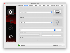
Si vous avez déjà utilisé l'assistant pour faire la configuration, vous pouvez compléter ici la configuration. Toutes les valeurs correspondent à celles que vous avez déjà mises dans l'assistant.
NOTE
A chaque fois qu'un paramètre est modifié, sa nouvelle valeur est immédiatement utilisée par le module mais pas sauvegardée. Tant que les paramètres ne sont pas manuellement sauvegardés, si le module est débranché les modifications non enregistrées serons perdues. (Voir l'onglet Backup)
Position
Sélectionnez la position dans laquelle le module est fixée au modèle. "(Voir la section 3 - Installation)"
Swashplate (Plateau cyclique)
Sélectionnez le type de plateau cyclique de votre modèle.
Dans la plupart des cas c'est le CCPM 120° ou CCPM 120° (reversed).
Dans l'émetteur, tous les mixages doivent être désactivés. Le mixage doit être le type H1 (servo unique)
Récepteur
Sélectionnez le type de récepteur que vous utilisez:
PWM – Récepteur standard.
PPM – Connexion à un fil.
Spektrum DSM2/DSMX – Satellite DSM2 ou DSMX.
Futaba S-BUS – Récepteur connecté via le SBUS.
Jeti EX Bus – Récepteur connecté via le Bus EX (pour l'intégration du modèle JETI)
SRXL/SUMD – Récepteur connecté via SRXL, SUMD, UDI.
Flight Style (Style de vol)
Configure le comportement du modèle en vol.
Ce paramètre est utilisé pour contrôler et adapter le comportement en vol en fonction des désirs du pilote.
Les valeurs faibles signifient que le modèle se comportera d'une manière plus homogène, plus contrôlée et donnera une sensation robotique. Les valeurs élevées apportent un comportement plus naturel. La réponse au mouvement des manches se rapprochera plus du comportement des hélicoptères à barre de Bell.
Ce paramètre n'a pas d'influence sur la stabilité du modèle. La plupart des pilotes préfèrent la valeur 4 par défaut.
Channels (Voies)
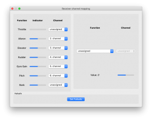
Après avoir cliqué sur le bouton "Channels", une fenêtre affichera l'assignation des voies. Vous pouvez assigner n'importe quelle voie à n'importe quelle fonction. Le nombre de voies disponibles dépend du type de récepteur. Pensez à n'assigner qu'une voie à chaque fonction.
Lorsqu'une voie est assignée à la fonction Gaz (Throttle), la commande des gaz sort sur le port AUX.
Lorsque une voie est assignée à la fonction Bank, alors la fonction de commutation de Bank est activée. (Voir le chapitre 5.6).
Lorsque la voie dédiée à la fonction Gyro Gain n'est pas assignée, il est possible de configurer le gain gyro directement dans l'onglet Sensor. La voie non assignée peut alors être utilisée pour une autre fonction comme la commutation de Bank (Bank switching).
Failsafe
Pour le types de récepteurs suivants: PPM, Futaba S-BUS, Spectrum DSM2/X, Jeti EX Bus, SRXL/SUMD, vous pouvez configurer le Failsafe directement dans le module. Les valeurs de chaque voie sont sauvegardées immédiatement en cliquant sur le bouton Set Failsafe. Si, pendant le vol, le signal est perdu durant plus d'1 seconde, ces valeurs seront utilisées automatiquement.
Avec les autres types de récepteurs, le Failsafe est programmé dans l'émetteur ou le récepteur.
Réglage en temps réel
En affectant un paramètre (P), il est possible de changer les réglages directement depuis l'émetteur. Vous pouvez changer simplement les valeurs du paramètre sélectionné en modifiant la valeur de la voie (par exemple avec un potentiomètre). Ainsi, vous n'avez plus besoin du logiciel de configuration. Un émetteur standard est suffisant.
Une modification de la voie correspondante changera immédiatement la valeur du paramètre. La valeur maximale de la voie donnera la valeur la plus haute du paramètre, tandis que la valeur minimale donnera la valeur la plus basse.
Le réglage du paramètre en temps réel a la priorité la plus élevée. Donc, lorsque cette fonction est activée, la valeur sauvegardée dans le profile ou la Bank sera ignorée.
Cette fonctionnalité est activée uniquement quand le logiciel de configuration n'est pas connecté. Cela empêchera des possibles confusions. Dès que le logiciel est déconnecté, la valeur du paramètre sélectionné est donnée pas la valeur de la voie. Si le logiciel est à nouveau démarré, il gardera la valeur obtenue par le réglage en temps réel dans sa mémoire. Cependant, le principe décrit plus haut sera toujours valable (le réglage en temps réel devient inactif et la valeur restera fixe même si la valeur est changée par l'émetteur)
Cette fonctionnalité permet d'utiliser simultanément 3 paramétres ou fonctions différents.
Si la fonction (F) est sélectionnée, elle est active lorsque sa valeur vaut 1. La fonction d'analyse de vibration permet de mesurer les vibrations pendant le vol. Ceci est détaillé plus loin dans la section concernant l'onglet Diagnostique.
Lorsque le réglage d'un paramètre est terminé, nous recommandons d'ouvrir le logiciel de configuration et de sauvegarder la valeur dans le module. Puis, désélectionnez le paramètre pour que sa valeur ne puisse plus changer.
NOTE
Il est recommandé de toujours faire extrêmement attention lors de l'utilisation de cette fonctionnalité pour ne pas perdre le contrôle du modèle.
5.3 ONGLET DIAGNOSTIC
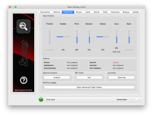
Une fois les réglages précédents effectués, il est maintenant recommandé d'effectuer tout ajustement et changement nécessaire dans l'émetteur pour que les contrôles de celui-ci s'accordent parfaitement avec ce qui est affiché. En général, chaque émetteur est différent et le centre des voies n'est jamais exactement identique. L'usure et l'environnement peuvent aussi amener des petites modification du centrage. Il faut aussi régler le maximum et le minimum de chaque voie. Pour cela, il suffit d'ajuster les fin de course des servos de chaque voie.
NOTE
Pour un bon fonctionnement du module, il est nécessaire de faire correspondre chaque voie avec la barre associée. La direction du mouvement doit, elle aussi, être la même.
Il est aussi nécessaire de vérifier les valeur des voies d'ailerons, de profondeur, de pas et d'anti-couple. Toutes ces voies doivent être centrée à approximativement 0%. Le module détecte automatiquement la position du neutre à chaque initialisation. Ne jamais utiliser les subtrim ou trim sur l'émetteur pour ces voies, car le module les considérera comme une action de l'utilisateur.
Assurez-vous que tous les subtrims et trims sont à zero. Il est aussi recommandé de régler les valeurs maximum et minimum.
Il est aussi recommandé de définir les valeurs maximum et minimum. Vérifiez les limites minimum et maximum pour toutes les voies. Si ces valeurs ne sont pas égales à -100% et 100% dans l'onglet diagnostic, il faut modifier les limites dans votre émetteur afin d'obtenir exactement ces valeurs.
Après ces ajustements, tout ce qui concerne l'émetteur est fait. Si certaines voies ont leur neutre qui bouge, cela peut signifier que les potentiomètres de l'émetteur ont du jeu. Ceci peut être compensé en augmentant la zone morte des manches (stick deadband) dans l'onglet Avancé (voir plus loin)
Si les valeurs pour les voies aileron, profondeur et anti-couple sont en gras, le système reconnait une commande pour bouger/faire tourner les axes.
Pour déterminer le Gain et le Mode du gyro d'anti-couple vous pouvez vérifier sur la valeur sur la barre Gyro. Les modes suivant soit disponibles:
- N – Mode normal
- HL – Mode conservateur de cap (Head lock)
- HF – Mode conservateur de cap avec fonction active. (Traité dans l'onglet Stabi)
ANALYSEUR DE SPECTRE
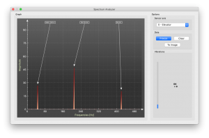
L'analyseur de spectre est un outil pour mesurer le niveau de vibration sur votre modèle. C'est un outil de diagnostic pour déterminer quelle est la pièce tournante qui cause un problème. Avec cette indication vous pouvez facilement identifier et réparer tout problème sur votre modèle.
Pour vérifier l'état du modèle vous pouvez voir la barre Vibrations. Elle indique le niveau général de vibration sur l'axe sélectionné.
Il est possible de mesurer les vibrations sur trois axes distincts:
- X - L'axe de profondeur (tangage)
- Y - L'axe d'aileron (Roulis)
- Z - L'axe d'anti-couple (Lacet)
- In-Flight - Rejouer les vibrations en vol
Le graphique mis à jour en temps réel montre les fréquences pour l'axe sélectionné. Il permet de voir la fréquence et l'amplitude des vibrations sur cet axe.
Les vibrations sont transmise à chaque axe en fonction de facteurs nombreux et variés. Les fréquences et amplitudes sont dépendantes du montage du modèle. En général, les vibrations sont les plus importantes sur l'axe Y (aileron) mais nous vous recommandons de vérifier chaque axe à chaque fois que vous faites la mesure. Cependant, les vibration ne doivent pas être supérieures à 50% quel que soit l'axe et à n'importe quel moment. Au cas où les vibrations sont supérieures à 90%, le modèle a un problème qui doit être résolu impérativement avant de voler. Même si le module Spirit FBL est très résistant aux vibrations, cela pourrait provoquer des comportements non voulus du module et provoquer des problèmes mécaniques. De telles vibrations peuvent décoller la Loctite et provoquer des casses mécaniques.
Niveaux de vibration:
- Vibrations jusqu'à 50% - les vibration on un niveau normal et acceptables
- Vibrations entre 50% et 90% - Niveau élevé de vibration
- Vibrations supérieures à 90% - niveau de vibration extrêmement élevé.
De la même manière que le niveau général de vibration ne doit pas excéder 50%, chaque pique de fréquence ne doit lui aussi pas dépasser 50%. Tout ce qui est au dessus de ce niveau doit être traité comme un problème et nécessite une investigation.
Pour comparer les graphiques, vous pouvez utiliser le boutton Freeze. Le graphique courant continue de s'afficher et le graphique capturé est sauvegardé et va apparaître en sur-impression. Ce dernier peut être supprimé avec le bouton Clear.
Il est possible de sauvegarder les graphiques de l'analyseur de spectre en utilisant le bouton To Image qui enregistrera le graphique courant comme une image.
L'analyseur de spectre est capable de détecter des vibrations jusqu'à 500Hz (cela correspond à des parties en rotation à 30000 tr/min)
Measurement procedure
- Remove main and tail blades from the model.
- Place the model on a suitable, soft surface (e.g. carpet, grass).
- Set blade pitch at approximately 0° on both main and tail rotors.
- Run the Spectrum analyser (this also freezes all servos).
- Spin up the motor to the usual flight RPM.
- Switch between the X, Y and Z axes, saving an image of each.
- Check vibrations in all axes.
- Stop the motor.
Recognizing vibrations
To recognize which component or part is causing abnormal vibrations it is necessary to determine the speed of the highest peaks. The main rotor will have the lowest speed and the tail rotor speed will be approximately 4.5x higher. Generally, the smaller the size of the model, the higher the headspeed will be.
In order to find out which part of the model is causing the unwanted vibrations, move cursor to the peak and check the head speed (RPM). The speed of the main rotor is usually in the range of 1500 to 3500 RPM. Therefore, if the speed is within this range, it is likely that there is a problem with the main gear, main shaft, main shaft bearings or rotor head itself.
Most excessive vibrations are usually, although not always, tail related. To check if there are vibrations coming from the tail you should find the frequency peak that is approximately 4.5x higher than the frequency of the main rotor.
Once you identify which part of the helicopter is causing the unwanted vibrations, you can gradually remove components of the suspect assembly, repeating the measurement process until the vibration disappears. Once the vibration levels have dropped to an acceptable level, you have found the suspect component and can replace it.
Measuring with tail blades installed carries some safety concerns and will also show increased levels of vibration.
NOTE
Gasser motors shouldn't be operated without load! Vibration measurement can't be performed without blades.
In-Flight - vibration analysis from flight
This feature allows you to record vibration spectrum from any moment of the flight. By selected channel you can tell the unit when the spectrum should be taken. The spectrum can be later viewer in the Spirit Settings software with the In-Flight option in the Diagnostic/Spectrum analyzer. Saved vibration spectrum will be stored until unit will lost the power. Saved record is rewritten on repeated activation.
For vibration measurement in the flight set the Special function in the General/Channels. Assign function F: Vibration analysis with axis you want to measure. Then select a channel which will be used for activation of the function.
As soon as the value is equal to 1 the vibration spectrum is saved. The record is saved exactly at the moment when function will change it's state from 0 to 1.
During flight it is enough to change state of selected switch of your transmitter (for example 2-state switch). After landing you can connect unit with the software and open the Vibration analyzer (select In-Flight axis to display the spectrum).
BEC TESTER
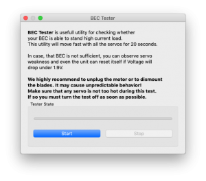
The tester is used for determining whether your power supply for the unit, receiver and servos is sufficient. The purpose is to achieve the biggest current spike and verify that your supply voltage will not drop under the safe level.
Click the Start button to start the test. After 20 seconds it should be finished.
If you will observe any issue, then your power supply is insufficient and should not be used. In this case power supply with higher current rating should used.
LOG VIEWER
The log is used to record events during flight. If a problem occurs and the reason isn't immediately known or evident, checking the log can help in identifying the issue.
It works in such a way that it records various events from the time the unit is powered on. If an event occurred you can see this in the log, reporting to the log is done every 10sec. When you click the Open log button you can see the current flight log which contains all the events from the last flight. When the power is disconnected, the log is cleared.
In the case of a major problem occurring during the flight ![]() , the log is then saved permanently to the unit's memory and remains there until such time as the log is opened.
If there is a saved log in memory, the user is advised with the message “Log from previous flight is available!” and the log from the flight when the problem occurred is opened. For example, when a signal is lost or the power supply failed you can find this in the log. The log from the first flight where the major problem occurred is always saved. If this is not opened, then it will not be overwritten with a newer one. In this state, the user is also notified by different cyclic pitch pump during the initialization process - elevator servo will change it's movement direction.
, the log is then saved permanently to the unit's memory and remains there until such time as the log is opened.
If there is a saved log in memory, the user is advised with the message “Log from previous flight is available!” and the log from the flight when the problem occurred is opened. For example, when a signal is lost or the power supply failed you can find this in the log. The log from the first flight where the major problem occurred is always saved. If this is not opened, then it will not be overwritten with a newer one. In this state, the user is also notified by different cyclic pitch pump during the initialization process - elevator servo will change it's movement direction.
The log can contain the following events:
- The model is in good condition. The unit did not recognize any problems.
-
- Sensor calibration was successful.
-
- Governor achieved requested RPM and is active from this moment.
-
- Cyclic achieved its maximum tilt angle. This indicates the model was unable to do the desired correction as necessary. In most cases it is not relevant. But it is possible that the value of the Cyclic Ring parameter is too low and the model can't rotate as fast as intended in the aileron/elevator axes. Alternatively, a too high value for rotational speed could be configured. It is also possible that in fast forward flight the model can pitch-up rapidly. We recommend to set this parameter as high as mechanically possible.
-
- The rudder servo reached its configured limit. When this event occurs before or after a flight it is not a problem. If you see this during flight it indicates that the rudder did not operate correctly. In most cases it is visible during flight as poor rudder response or “blow out”. If the model is set up correctly then it could be due to low rudder efficiency such as the tail blades being too short or headspeed too low. There is also the possibility of a mechanical issue or with the rudder limits being inadequate.
-
![]() RPM Sensor data are too noisy:
RPM Sensor data are too noisy:
- RPM readout is very unstable and are oscilating more than +/- 100 RPM. Data from the sensor are unusable for the Governor. Use additional shielding and mount a ferite rings. Increase value of the RPM Sensor filter parameter in the Expert settings.
-
- Received frame is unusable and will be ignored. In the most cases it does not present any problem. If the event is occuring often, then connection between receiver can be wrong or there is excess noise. Verify quality of the link and check the cable between unit and receiver.
-
- Sensor data reading failed - RPM sensor malfunction probably occured. Sensor is not sending data for 2 seconds or longer. Make sure, that the sensor wiring is correct and that the motor is spinning when Hold is disarmed.
-
- Signal lost suddenly. This problem should not occur at any time and must be resolved before the next flight. There could be a problem with the receiver and/or transmitter antennas. It could be a faulty receiver cable or the connection between the unit and receiver. In some cases signal loss can happen because of electrostatic discharge caused by static build up, this usually occurs in belt driven helicopters.
-
- The main loop was delayed. This can happen when wiring is incorrect or there is abnormal electrical noise interference with the unit, for example, from a BEC. If using the configuration software it could mean the link to the Spirit FBL unit is slower than it should be.
-
- Power supply voltage is lower than 2.9V. This mean you have to use a BEC that is capable of handling higher loads. In rare cases it could be faulty connections in cables.
-
- Vibration level achieved the level that is not normal and can affect integrity of the helicopter. During hard 3D maneuvers the event can occur more frequently.
-
All reviewed logs are saved as PDF files into Documents directory.
5.4 SERVOS TAB
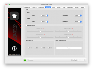
This tab is used for servo configuration, care should be taken to ensure correct frequencies are used and that the directions are set correctly.
Type
In this section, set the values for neutral pulse and frequency according to your servo manufacturer specifications.
For analog servos the frequency is usually a maximum of 60Hz.
Subtrim (tuning)
Ideally, without the rotor head installed, use a swash leveler to align the swash and servo horns so that the swashplate and servo horns are horizontal and perpendicular to the main shaft.
This is done by ticking the item Subtrim (tuning). This will put the Spirit FBL unit into a special mode where the collective position will be neutral with the servos centered. In addition, stabilization will be disabled.
Servos can easily be adjusted at this time. When completed, the swashplate should be exactly perpendicular to the main shaft and in addition collective pitch should be at 0° (it is possible to measure the pitch angle using a pitch gauge with rotor head and blades attached).
In most cases, it is also necessary for servo horns to be perpendicular to the main shaft. All servos, i.e., CH1, CH2, CH3 and CH4, are set separately on individual sliders. CH1 and CH3 are the aileron servos. CH2 controls the elevator and CH4 controls the rudder.
It is also necessary to set the subtrim and mechanics of the rudder so that the servo horn is perpendicular to its case and rudder pitch is at 0°. This setting will affect rudder stop performance.
Once set up, un-tick the Subtrim (tuning) check box to turn off this special mode.
After exiting the special mode, stabilization and rudder will work again. Be sure your collective pitch channel is configured correctly in the transmitter. That means you should see -100% to 100% in the diagnostic tab. Double check that 0% in diagnostic tab corresponds with middle position of your collective/throttle stick (with linear -100% - 100% collective pitch curve).
Cyclic servos reverse
This allows you to choose which servos should have their direction of motion reversed. While changing the collective pitch all servos should move in same direction. After this settings the model should react correctly to the sticks movement.
This parameter is the most important!
Servo travel correction
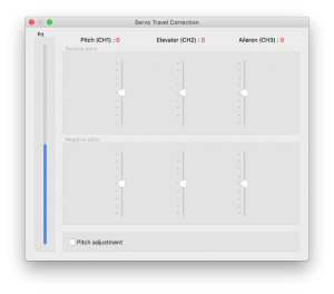
Here, you are able to modify and correct travel for each servo individually. Some servos are not very accurate in regards to travel at their limits and this inaccuracy may have a negative impact on flight characteristics. Once in this section of the software, the unit switches to a mode for doing these corrections.
It is expected that in the previous step, Subtrim (tuning), the swashplate was set at zero collective (0° rotor blades pitch). The procedure is such that you should use a swash leveler to determine whether there is any deviation on any of the servos in the lowest and highest points of collective throw. For both positive and negative positions, it is necessary to set the values separately – this is the reason for 6 sliders. If the travel is less than required, increase the value. If too much, decrease. To activate sliders in the secondary part move your collective to opposite direction.
This correction is also useful if there is asymmetric geometry on the helicopter causing issues such as the inability to achieve equal positive and negative pitch values. In this case, it is necessary to modify the positive or negative sliders for all three servos. If you are unsure about your settings, it is better to leave the sliders in the Middle. (position 0)
5.5 LIMITS TAB
This tab affects limits and servo travel ranges.
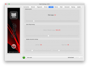
Cyclic Ring (tuning)
This parameter sets the electronic cyclic ring, which allows the model to achieve the largest cyclic ranges without mechanical binding (binding of servo horns, pushrods and linkages).
This parameter acts as a so-called electronic Cyclic Ring.
The settings here should be done very carefully to avoid damage to the model or it's associated electronics. Otherwise a boomstrike can occur.
First, set your desired collective range, for example, +/-12°. We recommend
using a -100% to 100% linear collective pitch curve in the transmitter.
Now it is time to set the Aileron/Elevator maximum cyclic pitch range.
Try to set the largest possible deflection. This parameter does not directly affect the speed of rotation, but if it is too low, the model may not have consistent pitch and roll rates.
This setting should be done with 0° collective pitch. Then carefully check
maximum stick deflection in all directions to ensure that mechanical binding
does not occur. This should also then be done with maximum and minimum collective pitch. Generally there is no reason to set deflection higher than maximum collective pitch angle. This parameter act as a so called Cyclic Ring.
If you increase the collective pitch range, this parameter must then be checked and in some cases adjusted to insure no binding occurs at your new maximum and minimum pitch ranges. If the selected cyclic ring range is insufficient, it is possible that pitch-up can happen during fast forward flight (even if the pitch-up compensation is at its maximum value). This is because the model will not be able to add sufficient corrections with the configured range.
Rudder end-points (tuning)
Left / Right limit - Sets the minimum and maximum deflection of rudder rotor blades.
We recommend setting these values for both directions to the maximum
allowed range by the manufacturer of the helicopter. Otherwise, the rudder
may not be able to keep the yaw direction during demanding maneuvers and
tail blow outs may occur.
Do not exceed allowed limit for your model.
5.6 SENSOR TAB
This tab is the last important part of the settings which must be configured.
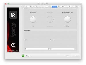
Sensitivity
The rotary dial adjusts the gyro sensitivity for aileron, elevator and rudder axes.
Cyclic gain – The higher the value is, the higher the accuracy within the control loop. The default value is preconfigured to 55% gain, for most models an optimal value of around 60% is suggested.
Rudder Common Gain– 100% means no multiplication. This is the recommended value for 550-class helicopters and smaller. For bigger helicopters it is often higher.130% could be fine. Transmitter gyro gain should be configured to approximately 60% for the first flight.
Rudder Gain – This parameter is enabled only in case of unassigned Gyro gain channel. It replaces function of Gyro gain from the transmitter, so you can directly set the value in the software.
Rudder Gain in the software or in your transmitter can be programmed in this way:
- Head-Lock mode: 1% to 100%
- Normal (Rate) or a special function: -100% to 0%
Negative gyro gain can be used to activate the rescue or the stabilisation modes – check the Stabi tab.
Rotation speed
The default value is 8 and will favor beginners more, the higher the value, the faster the rate of rotation. This factor also depends on the mechanical linkage ratio or D/R (Dual Rate) in the transmitter and also on the Aileron/Elevator limit.
Make sure the value is not too high else it can cause unwanted and inprecise movements.
default value - 8
We recommend to set the Cyclic rotation rate within a range of 8 - 11. Remember that DFC rotor heads tend to rotate faster so it's better to initially start with a lower value for them.
For the Rudder rotation rate pilots are preferring a range of 9 – 11.
5.7 STABI TAB
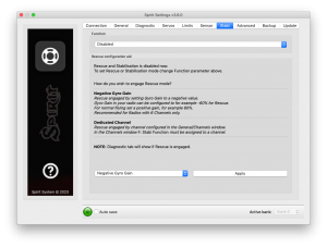
The Spirit unit offers you the options of model stabilization and rescue mode.The stabilization function, once activated, will recover the model to a horizontal position without any other input from the pilot, this can be used as a “bail-out” feature when trying new maneuvers and can help with the learning process.
Rescue mode complements the normal operation of the Spirit unit. If activated, the model will recover to a horizontal position and add collective pitch as per the settings. This function can be used any time when the pilot loses orientation or control of the model.
The Spirit unit allows you to assign a stabilization or rescue mode using the gyro gain channel. 0 - 100% gain in the transmitter is always heading lock gyro mode and with -100 – 0% gain, you are able to activate stabilization or rescue mode. This means that instead of normal (rate) mode, it will stay in heading hold gyro mode, plus rescue/stabilization is activated. So, while rescue/stabilization mode is activated, a gyro gain of -70% is considered as 70%. This behavior can be also observed in the Diagnostic tab.
Some transmitters have a gyro range of 0 to 100% where 50% is the middle - zero gain (e.g. Spektrum DX6i). Others use a range of -100% and 100%, where 0% is the middle.
Function
Here is where you select which mode should be activated at negative gyro gains.
Disabled - Normal (Rate) gyro mode.
Rescue (Normal) - Recovers the model to an upright horizontal position – skids always to the ground. This recovery mode is great for the beginners.
Rescue (Acro) - Recovers the model to a horizontal position, inverted or upright, whichever is closer at the time of activation. For intermediatte and advanced pilots that are flying acrobatic manouvers.
Stabilization (Normal) – stabilization mode - skids always to the ground. This mode is good for learning the basics such as hovering and slow transitions. Model is always pushed to the horizontal position.
Stabilization (Acro) – stabilization mode - inverted or upright, whichever is closer at the time of activation. This mode is used for learning the basics of acrobatic maneuvers. If the sticks are in the center, the model has tendency for returning to the horizontal position.
Stabilization (Scale) – stabilization mode - skids always to the ground. This mode is used for a scale flying. Gyro mode is Normal (Rate).
Coaxial – stabilization mode - inverted or upright, whichever is closer at the time of activation. The steering behavior is very similar to a coaxial helicopters. Great for learning a hovering practices.
If using these modes, be sure your helicopter is initialized on a flat surface, not tilted to any side. Do not tilt the helicopter for more than 5 seconds.
The rescue mode is very demanding on the BEC. Be sure your BEC can handle such peak loads. In case it is is not sufficient your model could crash! Never exceed angles recommended by manufacturer of the model, else the mechanics can be damaged during the flight!
Flybar mechanic
If your helicopter is equipped with traditional flybar mechanics, you have to enable this parameter in order to use the stabilization or rescue modes. All settings are the same for flybarred helicopters except this parameter.
Flybarless helicopters must be configured and operated with the Flybar mechanic parameter disabled!
Rescue collective pitch
This determines how fast the model will ascend during the rescue mode.
100% means the maximum deflection of the blades, which was configured in the Servos tab.
It is very important to check whether the rescue mode works correctly before the first flight (on the bench without the motor/rotors running).
Collective pitch should be always positive with the rescue engaged - while helicopter is on the ground
Sticks priority
Specifies the amount of control while configured mode is activated.
The higher the value, the more the model will react to stick movements.
Direction control rate
This specifies the rate of controlling direction for the stabilization mode.
Low values are well suited for beginners to get coaxial like behavior. Higher values are more appropriate for scale flying.
Acro Delay
Specifies a time period for the Rescue (Normal), when the model is recovered from the inverted flight. Until the period is reached, the rescue has the same behavior as the Rescue (Acro). In this way, faster ascending to a safe level can be achieved.
5.8 ADVANCED TAB
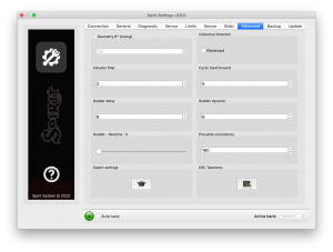
This tab is for more advanced configuration of the Spirit FBL unit. It is recommended that you fully understand these parameters before adjusting them. However, it is essential to set geometry. Other parameters, however, depend on the preferences of the pilot.
Geometry 6° (tuning)
For proper operation of the Spirit unit, it is necessary to set this parameter correctly. Here, the unit is switched to a special mode for settings 6° of cyclic pitch on the main blades. It is necessary to set the value so that the blades angle is at 6° in the aileron axis. You need to rotate your rotor head with blades to be parallel to the longitudinal axis of the model. A higher value increases the angle; a lower one decreases the angle. Optimal head geometry should be in the range of about 90 – 160. If not in this range, it is recommended to adjust the distance of a ball link on the servo horns or perform other mechanical adjustments.
Collective Direction
Parameter to determine direction of the collective pitch.
In case of a Trailing Edge rotor head or if a mixing arms are present on the rotor head, tick the Reversed option. In the most cases the parameter is unticked.
Correct configuration is very important, else the collective pitch will be reversed.
Elevator filter
This parameter compensates elevator bouncing during aggressive maneuvers. The larger the value, more compensation is involved.
If this value is too high it can lead to a soft feeling in the elevator. We recommend using the default value of 1 to begin with.
Cyclic feed forward
This parameter is used to set amount of direct feel between your sticks and
your model helicopter. The higher the value, the more aggressive the model
will feel and the faster the model will react to stick movements.
If the value is very high, elevator bounce-back effect can occur.
During a tic-toc maneuver you can also observe higher motor load or aileron oscillations, because the model is unable to react fast enough.
Setting this value too high can result in elevator bounce.
If the model feels disconnected and there is a lag between stick inputs and
the model, try increasing this value.
Rudder delay
This is a parameter to smooth rudder movements. It also helps to stabilize the rudder – it is a kind of electronic damping. The faster the servo is, the lower the tail delay should be. For analog servos it is recommended to set this value to around 20-25. For usual digital servos it is mostly between 10 – 15. For very fast servos (~0.04s/60°) the value is 5. In case of a brushless servos it is recommended to set a value of 0 - 2.
If the value is too high, the rudder could start to oscillate or wag or could cause a slow rudder stop.
Rudder dynamic
If the rudder does not stop correctly, for example it overshoots, this behavior can be changed with this parameter.
6 – is the default value.
The larger the value, the more aggressive the behavior of the tail. If the tail overshoots in stops, the value is too high. This parameter also affects the response speed of the stick movement; a higher value means a faster response. If you cannot reach a symmetric stop on both sides you will need to make sure that the tail is centered at 0°. Alternatively, you can lower the rudder limit for that side.
Rudder – Revomix
Revomix (tail pre-compensation) adds rudder in response to collective pitch changes, when the tail needs increased holding. Revomix is independent of the transmitter. By default it is turned off, the user must set the amount required of the pre-compensation.
Allowed values are 0 to 10 with 0 being disabled; in most cases it is not necessary to use this parameter, however, when using low headspeed or on helicopters with a poor performing tail, this setting can be used.
Pirouette consistency
This parameter determines the consistency of pirouettes and holding performance. If pirouettes are not consistent during certain maneuvers, increase the value of this parameter.
This value is individual for every model, it depends on many factors such as: your rudder mechanics, head speed, etc. Before setting this parameter, it is recommended to first set the gyro gains.
If the value is too high, the tail can oscillate or wag. It can also cause poor stop performance. This value should be between 150 and 180.
For brushless servos it is recommended to increase value by 10-15 points.
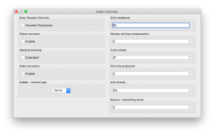
EXPERT SETTINGS
For fine tuning you can set the following parameters. Normally it is not needed to configure any of these parameters.
Rotor Rotation Direction
Parameter to determine rotation direction of the main rotor. In the most cases it is in the clock wise direction - parameter is unticked.
Stick deadband
Determines the area, around center stick, where the system does not recognize any stick movement. If channel readings are inprecise the value should be increased. This can be verified in the Diagnostics tab. This parameter does not replace the Exponential function.
Elevator pitchup compensation
If, during fast forward flight, the model reacts to inputs too rapidly or if the model pitches up, increase this value until this no longer occurs. If the helicopter pitches up abruptly, this could be caused by a cyclic range that is too low and/or too much collective pitch. In this case, you will have to increase the Aileron/Elevator range as high as the model can handle without any binding. If this doesn't fix the problem, you can add more pitch-up compensation.
Cyclic phase
The value indicates the angle by which the swashplate is virtually rotated.
For example a value of 90 will rotate the elevator to aileron. This feature is recommended for models with multi-blade rotor heads. For most other models, we recommend a zero value.
Pitch Pump Booster
To achieve flybar-like collective pitch behavior, you can increase the value until desired feeling is achieved. Remember that higher values are too demanding for power supply and servos on the model.
Signal processing
This parameter is used for operation on models with extreme vibrations that can't be eliminated in any way. This should be enabled only in cases when is absolutely necessary, because flight performance could be affected. It should increase precision of flight and also the precision of rescue and stabilization modes.
RPM Sensor Filter
In case that your RPM sensor has noisy output then RPM readout can be very unstable. This can lead to various problems with Governor. There may be a problem with spool up, flight mode switching or head speed jittering. To make RPM readout very precise, you may need to increase the value.
On the other hand, too high value can lead to a delay, that is unwanted for optimal Governor performance. So the value should be as low as possible while RPM readout is still precise. Variation of 1-20 RPM against the Requested RPM is optimal.
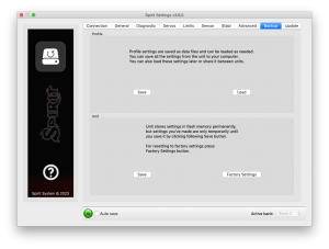
5.9 BACKUP TAB
Here, you can save the settings to your Spirit unit before powering off, you can also save the settings to your computer here, Should you need to reload them at a later date.
Profile
This section allows you to Save and Load complete settings of the unit to a specified file. If you have more than one of the same model, it is not necessary to carry out a complete setup again, just load the stored settings easily with the Load button.
Unit
Any changes to the configuration can be saved at any time to the internal flash memory of the unit.
To put all settings to a factory defaults, click Factory Settings.
Remember to save the settings each time you want to store the settings permanently. You must press the Save button. Otherwise, the changes will be lost after the Spirit FBL unit is turned off.
Bank Switching
In case that the Bank Switching is enabled, you can save the settings from single bank or even all banks. To see the differences between Banks you can use Bank Comparison feature.
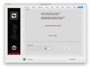
5.10 UPDATE TAB
If you want to update the firmware, you can do so in this tab.
Firmware
First select the data file containing the firmware (*.4df) – Select button.Once the file is selected, press the Flash button. The upgrade progress will be displayed here. After completion, a confirmation dialog box should indicate a successful update.
Then, unplug the unit from its power source.
Upon the next start it will load with the newly flashed firmware.
Configuration of the unit is not changed, so you do not need to save/load it.
You can get firmware from: spirit-system.com.
6 BANK SWITCHING
This functionality allows you to switch between saved settings during a flight. Switching is done through the transmitter, so that channel's value is changed. This mean that a Bank can store one unique settings. The unit is able to store 3 different banks.
With a transmitter you are able to use a three position switch to switch freely between banks.
Bank switching is disabled by default, so you can decide whether it is useful in your application. You have to activate it by the assignment of Bank function in the General/Channels window. Generally, it is assigned to channel 7.
Bank 0 – active in range of lower third (impulse under 1400μs).
Bank 1 – active in range of mid third (impulse between 1400μs to 1640μs).
Bank 2 – active in range of upper third (impulse above 1640μs).
Initial settings for Bank 1 and Bank 2 are equal to Bank 0. Bank 0 allow you to configure all parameters, while Bank 1, 2 does not allow to set main parameters. For safety, Bank 1 and 2 does not allow you to set any main parameters.
The Bank switching is great for switching between flight styles, sensor gains for low or high RPMs, for slow acro or 3D. Alternatively it can be used just for tuning your settings.
If the software is connected with the unit then bank switching via the transmitter is disabled. Then, Bank switching is performed using the software in bottom part of the window. When a bank is switched using the software it is necessary to save your settings to the unit before you switch Banks, or your settings will be returned to the previous (unchanged) state.
7 GOVERNOR
From firmware version 1.2 governor feature is available! You can use this feature instead of internal governor from your ESC or other governor. It is designed to work with electric, nitro and gasser helicopters. This can make flight performance even better because of constant head speed.
To achieve proper function it is very important to configure your ESC and then the unit. First from all make sure that internal governor is disabled in the ESC.
It is necessary to disassemble rotor blades from your model prior to the governor setup. Do not make any adjustments with motor turned on.
Governor feature can be used with the following receiver types:
Spektrum DSM2/DSMX, Futaba S-BUS, Jeti EX Bus, SRXL/SUMD.
It is necessary to use throttle output from the unit when using governor. Throttle output is at the AUX port. You must connect the ESC or throttle servo there.
7.1 Sensor Wiring
Signal from a RPM sensor should be connected to the PIT pin (middle pin of the ELE/PIT/AIL port).
- ESC with RPM output
- For electric helicopters the best and the easiest solution. You can use RPM output cable that is present on the ESC.
- ESC without RPM output
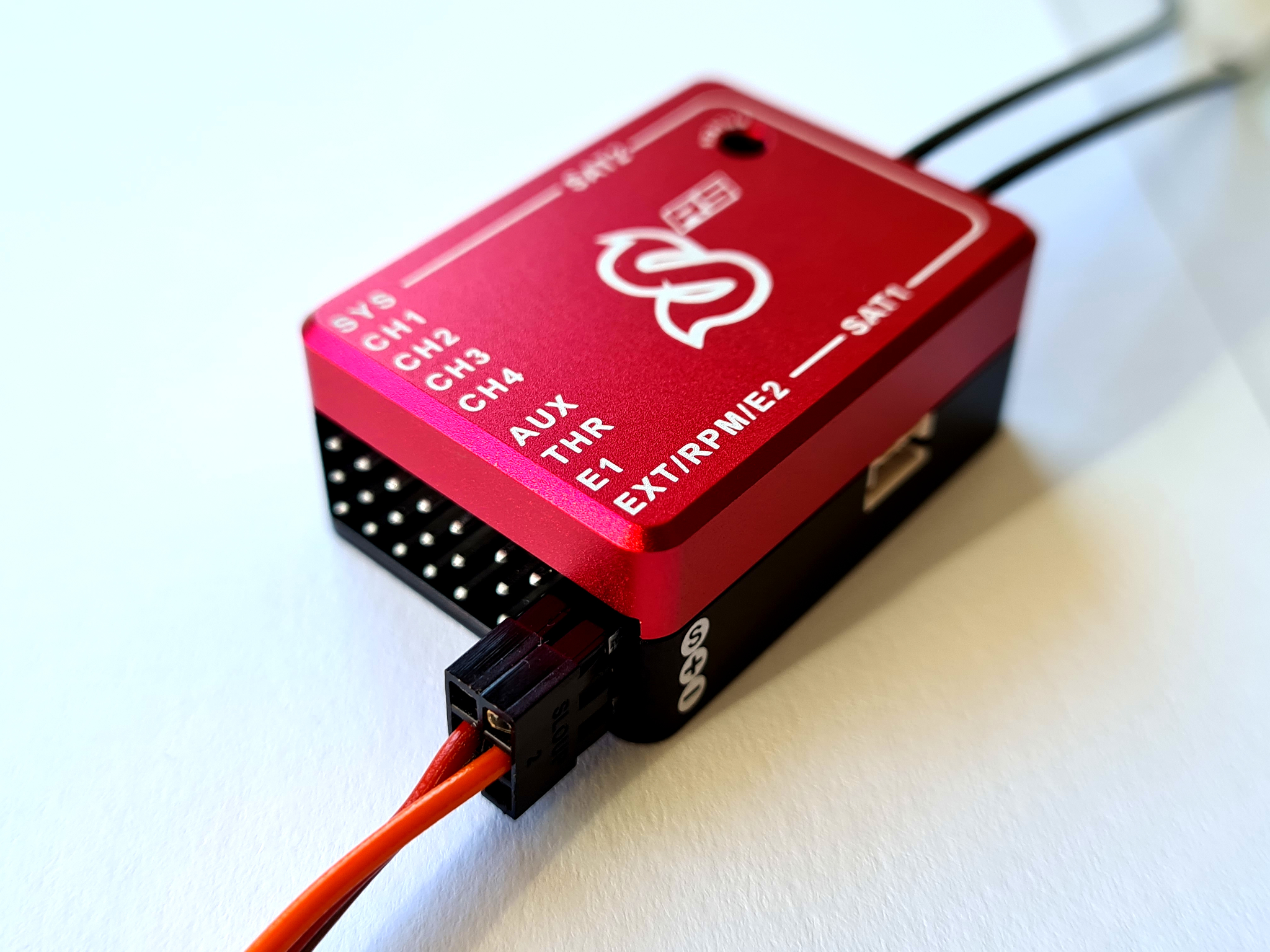
- In case that your ESC has no RPM output you will need a separate RPM sensor that can be connected to phases of the motor. Important is to power the sensor properly. Voltage can't exceed allowed level for the sensor. Recommended voltage range can be obtained from the sensor manufacturer. In case that the sensor require 3.3V you can connect it to the satellite connector in the unit (Details in the following photo). You can also use the Spektrum adapter.
- In case that the sensor is powered improperly it can be damaged along with the unit.
- Magnetic sensor
- For Combustion helicopters is necessary to use a sensor working on principle change magnetic field. In case that your ESC has no RPM output you will need a separate RPM sensor that can be connected to phases of the motor. Important is to power the sensor properly. Voltage can't exceed allowed level for the sensor. Recommended voltage range can be obtained from the sensor manufacturer. In case that the sensor require 3.3V you can connect it to the satellite connector in the unit (Details in the following photo). You can also use the Spektrum adapter.
- In case that the sensor is powered improperly it can be damaged along with the unit.
Red (+3.3V), Brown (GND).
7.2 Prerequisites
Electric
- Set throttle range in your transmitter so that 0% and 100% throttle position matches with value of the throttle bar in the diagnostics tab. This can be done by Subtrim function in your transmitter and/or Travel Adjustment function.
- Re-calibrate throttle range according to instructions of your ESC. In the most cases it can be configured by powering the model with throttle stick with 100% throttle and then by moving the stick down to 0%.
- If possible, configure fast spoolup mode in the ESC so the governor will be unaffected.
Nitro / Gasser
- Set the throttle range in your transmitter so that 0% and 100% throttle position matches with value of the throttle bar in the diagnostic tab. This can be done by Subtrim function in your transmitter and/or Travel Adjust function.
7.3 Activation
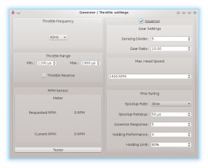
To activate Governor feature in the unit, you will need to assign Throttle function in the General tab/Channels. Then you will be able to enter Governor Settings in the General tab.
7.4 Settings
First from all basic settings are necessary so the governor can control the head speed correctly.
Throttle frequency
To achieve the fastest governor reaction it is necessary to set the highest possible frequency. For ESC it could be only 60Hz, but mostly all can work even with 200Hz. If you are unsure, please contact manufacturer of the ESC. For combustion helicopters it is max. operating frequency of the throttle servo.
Throttle Range
This parameter can affect output from the unit so you can fine-tune ranges precisely. For electric helicopters this parameter is optional. But in case that your ESC does not allow to calibrate throttle range correctly, you can do so here. For Nitro and Gasser helicopters you have to configure it always so the Throttle servo range matches range for the motor.
Throttle Range - Min.
Value of the lowest throttle signal. Default value: 1100 μs. For electric helicopters this value should be specified by manufacturer of the ESC. It is often specified in value of miliseconds (ms).
You should set the lowest position when the motor is not spinning up anymore – is halted. While configuring this, the motor can start so you have to be very carefull.
Throttle Range – Max.
Value of the highest throttle signal. Default value: 1900 μs. For electric helicopters this value should be specified by manufacturer of the ESC. It is often specified in value of miliseconds (ms).
The value should be configured to match with 100% throttle output programmed in your ESC or full throttle of the motor. If this parameter is not high enough you will be unable to tune Governor because there will be not enough room to compensate high loads. If configured too high then you can observe that after high load head speed will not drop immediately but can be there even for few seconds.
Throttle Reverse
Especially for Nitro and Gasser motors you can set correct compensation direction for the servo here.
Gear Settings - Sensing Divider
Electric motor: Motor poles / 2. For a 10 pole motor set divider to number 5. Mostly configured to 3 – 5.
Nitro/Gasser motor: Number of all active magnets. Mostly it is 1 – 2.
Gear Settings - Gear Ratio
Gear Ratio of the helicopter between the main wheel and pinion of the motor. For example: 120T main gear / 12T pinion = 10.
Max. Head Speed
Configure max. head speed that should be achieved with 100% throttle curve. For example: If you know that you won't exceed 2500 RPM then you can set the value to 2500. With 80% throttle curve your head speed will be 2000 RPM (2500 * 0.80 = 2000).
Fine-Tuning – Spoolup rate
Configure speed of the motor spoolup. For initial tests we recommend Slow spoolup rate.
Fine-Tuning – Spoolup Rampup
Value that will be added at the beginning of motor spoolup – when Hold is turned off. If the spoolup is not smooth, i.e. motor will start with a kick, the value is too high. If the spoolup has a delay, the value is too low. Default value of 50 μs should work fine in the most cases.
Fine-Tuning - Governor Response
This parameter is the most important one to achieve fast and proper response of the governor. It determine how fast the governor should react to a short-term load. Thus optimal settings are required. If configure too low or too high, rudder will not hold properly and can oscillate. Governor can greatly affect rudder performance so you can achieve better holding behavior. Too high value will result in overspeeding during e.g. pitch pump.
Fine-Tuning - Holding Performance
Determine how well the head speed is maintained during a long-term load. If value is too low then during e.g. tic-toc maneuver head speed can drop gradually. In case it is too high then after the tic-toc head speed can be higher than necessary and can even return to requested RPM with noticeable delay. It is better to start governor tuning process with low value.
7.5 Fine-Tuning Procedure
Firstly you have to finish basic setup including Max. Head Speed. Throttle curve in the transmitter must be FLAT. We recommend to set the throttle curve for example to flat 70%, 80% or 90%.
After disarming Throttle Hold you should immediately see Requested RPM in the software – this is desired head speed that should be maintained. Current RPM is head speed that is currently on the rotor head. If Current RPM is not calculated properly, then there is a problem with Gear Settings. In case that you can see zero or random Current RPM value then there is a problem with RPM Sensor and must be fixed.
Performance tuning procedure
We recommend to set the following values for the beginning:
- Governor Response: 5
- Holding Performance: 1
- You should start with increasing the Governor Response. You can do so until RPM is constant enough while doing aggressive collective pitch changes during hovering. When you will notice an overspeeding (RPM is higher than initially was) then the value is too high. In case that the value is too low or too high then the rudder performance can be affected negatively as well.
- When the Governor Response is well tuned, you can continue with increasing the Holding Performance parameter. In case that the value is too low, you will notice poor holding performance during demanding maneuvers with longer duration such as loop or tic-toc. If the value is too high, you can observe that the head speed is unstable even during stationary hovering.
Governor Response: 6 and Holding Performance: 5 may work fine for wide range of the helicopters.
NOTE
- Throttle calibration of the ESC is possible only if the Governor is disabled in the unit.
- For throttle curve under approx. 50% governor is inactive – throttle is controlled directly.
- You should see “Governor was Engaged” event in the log after spoolup with enabled governor.
- Governor Bailout function can be activated whenever the throttle signal is higher than 1250 μs which is approx. 12% throttle curve. If the signal is lower then smooth spoolup sequence is activated.
- In case that the Current RPM value is 4000 RPM measurement is out of range. It may be needed to change count of the active magnets.
- If governor does not react correctly during Throttle Curve changes or even during spoolup, it is most probably result of an excess noise in the RPM sensor or connection. You may consider to use a proper shielding. Increasing value of the RPM Sensor filter in the Expert settings can solve the problem.
- List of the supported RPM sensors and their wiring will be updated on the forum.
8 SOFTWARE KEYBOARD CONTROL
For fast and easy configuration we have implemented keyboard controls in the software.
| Shortcut | Function |
|---|---|
| F1 to F10 | Switch between tabs. |
| ESC | Exit current window. |
| CTRL + S | Save settings to the unit. |
| CTRL + P | Save profile to your computer. |
| CTRL + L | Load profile from your computer to the unit. |
| CTRL + W | Connection settings for the Wifi-Link module. |
| Numpad 0, 1, 2 | Switch between banks. |
| Tab | Switch between parameters. |
| Space | Select parameter / option |
| Arrows | Increase / Decrease value. |
| Page Up / Page Down | Increase / Decrease value by tens. |
| Home | Set the lowest value. |
| End | Set the highest value. |
