Difference between revisions of "GeoLink Mounting/ru"
(Created page with "Никогда не монтируйте GeoLink прямо на толстые металлические детали, рядом с двигателем или сервоп...") |
(Created page with "''Пример:'' Расположение '''Горизонтально (0°)''' . Основной ротор слева.") |
||
| Line 39: | Line 39: | ||
[[File:geolink-horizontal.jpg|thumb|center]] | [[File:geolink-horizontal.jpg|thumb|center]] | ||
| − | <center>'' | + | <center>''Пример:'' Расположение '''Горизонтально (0°)''' . Основной ротор слева.</center> |
<br/> | <br/> | ||
Revision as of 12:10, 15 October 2018
Правильный монтаж - залог надежной работы модуля. Если он выполнен неправильно, GeoLink не сможет обеспечить точность позиционирования или даже не смогут работать некоторые функции.
Пожалуйста, обратите особое внимание и тщательно выполните следующие шаги.
Contents
1 Монтаж на вертолете
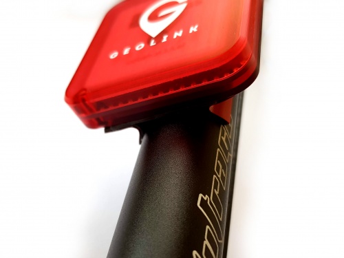
Модуль должен монтироваться строго горизонтально так, чтобы логотип GeoLink находился сверху. Вы можете выбрать одну из двух позиций:
- Горизонтально (0 °) - разъем указывает на основной ротор
- Горизонтально (180 °) - разъем указывает на хвостовой ротор
Перед фактическим монтажом ознакомьтесь с разделом Выверка.
1.1 Где размещать
Идеальное место размещение модуля GeoLink - хвостовая балка. Обычно это наилучшая позиция для достижения качественной работы. Оптимальное положение должно соответствовать следующим критериям::
- Дальше 5 см от твердых токопроводящих частей, таких как карбоновая рама или болты
- Дальше 5 см от любой электроники (особенно сервоприводов)
- Дальше 8 см от электродвигателя
- Дальше 30 см от какого-либо магнита (особенно магнитных держателей канопы)
- Небо в прямой видимости
- Расположен идеально в горизонте
Выберите не слишком далекое от Spirit размещение модуля, учитывая длину провода. Размещение модуля на хвостовой балке слишком далеко от основного ротора может привести к смещению центра тяжести модели.
1.2 Как крепить
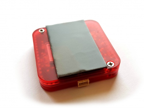
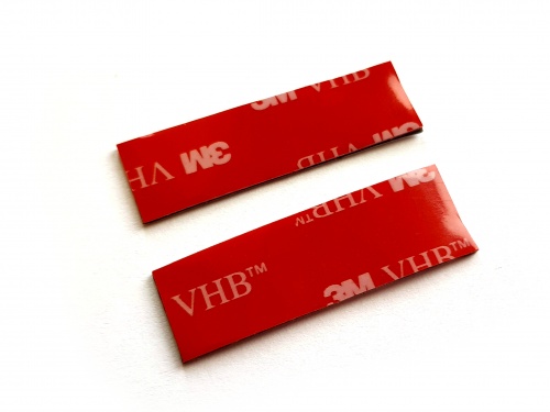
Установка модуля обычно выполняется с помощью двухстороннего скотча из комплекта. Скотч держит очень крепко и достаточно будет всего двух кусочков.
Некоторые вертолеты имеют балку более сложной формы ,чем просто труба. В этом случае есть вероятность, что вам придется потратить больше времени, чтобы установить модуль.
При желании вы можете использовать сторонний крепеж для модулей GPS.
Никогда не монтируйте GeoLink прямо на толстые металлические детали, рядом с двигателем или сервоприводом.
Each circuit containing antennas is very carefully designed to achieve correct impedance. Impedance is electrical property which is directly determining performance of antenna. Impedance is changing immediately by placing any parts close to the circuit, especially near antenna. Because PCB is acting as a part of GPS antenna any change to the PCB, including screws has noticeable impact. Thus we highly do not recommend doing any hardware changes to GeoLink module.
1.3 Mounting with provided tape
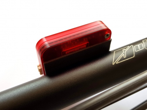
1. Take the first piece of tape and glue it approximately in the middle.
2. Attach the module at the tail boom.
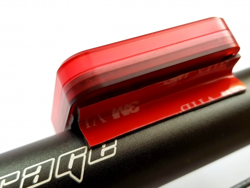
3. Divide second piece of tape.
4. While holding folded tape in two fingers insert it between module and boom to create support (from both sides). With a finger or a tool try to insert both pieces as far as possible so that adhesive surfaces are holding well.
The tape will shortly adhere on the surface tightly and can't be reused anymore.
1.4 Unmounting
In some cases pilot might need to remove GeoLink from a model, for example during a repair. When provided double sided is used a special care must be taken!
Always try to pull out double sided tape first, not the module. Lastly rotate with the module gently until double sided tape will peel off.
Never pull the module in any way when mounted with double sided tape! This could bent or crack the plastic enclosure.
1.5 Mounting examples
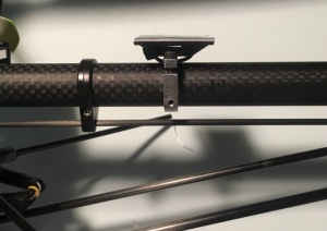
Mounting can be done also in other ways. Please see following photos.
1.5.1 LYNX Oxy 2
1.5.2 KDS Chase 360
1.5.3 SAB Goblin 700
2 Wiring
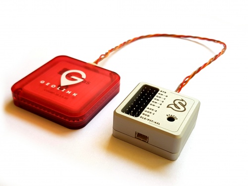
Wiring is done through one JST to JST cable with length of 22cm which is supplied with GeoLink. Longer cable is possible and will be available. For GPS itself a shorter cable is better, because any additional cables attached to the module and Spirit unit could distort the signal.
μSpirit SAT - Satellite port Spirit Primary satellite port Spirit Pro Secondary satellite port
3 Alignment
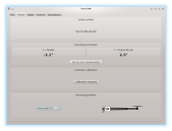
Since it is uneasy to visually align the module perfectly, the GeoLink has built-in digital level in the Spirit Settings. There you can see how to align the module and perform a necessary adjustments.
3.1 Alignment procedure
Alignment can be done prior the mounting or even later, as needed.
- Connect GeoLink and Spirit unit with provided cable (while GeoLink being not mounted yet).
- Power up the Spirit unit.
- After initialization start the Spirit Settings software.
- Open General tab - GeoLink module settings.
- Move to the Module tab there.
- Place GeoLink at a flat, aligned horizontal surface anywhere on your model in order to get a precise reference. (for example the Spirit unit)
- Click Set as zero (temporarily) button to reset angle of built-in protractor.
- Move GeoLink to a desired mounting position.
- Mount it with provided double sided tape at position ideally with 0° deflection.

