Difference between revisions of "Wiring"
(Marked this version for translation) |
(Marked this version for translation) |
||
| (82 intermediate revisions by 2 users not shown) | |||
| Line 1: | Line 1: | ||
| − | <languages /> | + | <languages /> |
<div id="up"></div> | <div id="up"></div> | ||
<translate> | <translate> | ||
<!--T:1--> | <!--T:1--> | ||
| − | Spirit can be used as a standalone tail gyro or as a flybarless system | + | Spirit can be used as a standalone tail gyro or as a flybarless system or as a flybar stabilisation unit.</translate> |
| − | + | ||
| − | + | ||
| − | + | ||
| − | + | ||
| − | + | ||
| − | + | ||
| − | + | ||
| − | + | ||
| − | + | ||
| − | + | ||
| − | + | ||
| − | + | ||
| − | + | ||
| − | + | ||
| − | + | ||
| − | + | ||
| − | + | ||
| − | + | ||
== <translate><!--T:7--> | == <translate><!--T:7--> | ||
| Line 35: | Line 17: | ||
<!--T:10--> | <!--T:10--> | ||
| − | Even if you do have a flybarred model, you can also connect the unit in the same way as a you would a flybarless one. This allows you to use the full potential of the unit including Stabilization and Rescue mode. In order for this to work correctly, it is necessary to | + | Even if you do have a flybarred model, you can also connect the unit in the same way as a you would a flybarless one. This allows you to use the full potential of the unit including Stabilization and Rescue mode. In order for this to work correctly, it is necessary to enable the ''Flybar mechanic'' parameter in the Advanced/Expert window during setup. All other parameters can be configured just the same as with a flybarless head.</translate> |
| Line 51: | Line 33: | ||
| − | {| style=" | + | == <translate><!--T:74--> |
| − | |<span style="color:red">'''Spirit'''</span> | + | CONNECTOR ORIENTATION</translate> == |
| + | |||
| + | <translate><!--T:118--> | ||
| + | Before plugging-in any connector to the Spirit unit please check carefully following instructions. See how to connect all cables in the right orientation with respect to Spirit unit you have.</translate> | ||
| + | |||
| + | === μSpirit === | ||
| + | {{Quote|<translate><!--T:93--> | ||
| + | Pin layout of the '''JST-ZH(R) connectors is different''' from standard Servo connectors. BROWN (Middle) wire is GND pin. ORANGE wire is SIGNAL pin. RED wire is +5V (BEC voltage). By using '''JST-Servo''' cables you can connect a classic Servos and all Spirit peripherals to the μSpirit even with Servo connectors.</translate>}} | ||
| + | |||
| + | [[File:uspirit-polarity.png|280px|center]] | ||
| + | |||
| + | === <translate><!--T:117--> | ||
| + | Spirit and Spirit Pro</translate> === | ||
| + | |||
| + | <translate> | ||
| + | <!--T:75--> | ||
| + | All cables connected to the unit must be oriented so that the signal wire (ORANGE wire) is closer to the connector pin label, towards the center of the unit. This orients the negative (BROWN wire) toward the edge of the unit.</translate> | ||
| + | |||
| + | [[File:spiritpro-polarity.png|300px|center]] | ||
| + | |||
| + | === Spirit 2, Spirit RS, Spirit GT, Spirit GTR === | ||
| + | |||
| + | <translate><!--T:119--> | ||
| + | All cables connected to the unit must be oriented so that the signal wire (ORANGE wire) is at the top of the unit. This orients the negative (BROWN wire) at the bottom of the unit.</translate> | ||
| + | |||
| + | |||
| + | == <translate><!--T:120--> | ||
| + | SERVOS WIRING</translate> == | ||
| + | |||
| + | <translate><!--T:121--> | ||
| + | Spirit units have full support for all types of servos. Please proceed according the Setup Wizard in Spirit Settings software to see how to connect the servos properly.</translate> | ||
| + | <p></p> | ||
| + | {{Quote|'''<translate><!--T:3--> | ||
| + | Spirit is pre-programmed to 1520µs servo neutral impulse and 50Hz frequency – please ensure you have the correct servo parameters selected as specified by your servo manufacturer.</translate> | ||
| + | <br/> | ||
| + | '''<translate><!--T:4--> | ||
| + | If the neutral impulse of your servo/s is different to the above, such as 760µs, do not connect this servo yet as it could be damaged.</translate>''' | ||
| + | }} | ||
| + | |||
| + | <translate><!--T:5--> | ||
| + | Some connectors have non-standard dimensions that could interfere with neighboring connectors after plugging in the unit. As a solution, we recommend replacing these connectors with JR or Futaba type.</translate> | ||
| + | |||
| + | '''<translate><!--T:6--> | ||
| + | Never plug a connector for powering the unit into the SYS or ELE/PIT/AIL positions or you may risk damaging the unit.</translate>''' | ||
| + | |||
| + | |||
| + | <p></p> | ||
| + | {| style="width:75%;" | ||
| + | |<span style="color:red">'''μSpirit'''</span> | ||
| + | |- | ||
| + | |''CH1'' – <translate> | ||
| + | <!--T:83--> | ||
| + | Pitch / Aileron servo</translate> | ||
| + | |- | ||
| + | |''CH2'' – <translate> | ||
| + | <!--T:84--> | ||
| + | Elevator servo</translate> | ||
| + | |- | ||
| + | |''CH3'' – <translate> | ||
| + | <!--T:85--> | ||
| + | Aileron / Pitch servo</translate> | ||
| + | |- | ||
| + | |''CH4'' – <translate> | ||
| + | <!--T:86--> | ||
| + | Rudder servo / Rudder ESC</translate> | ||
| + | |} | ||
| + | <p></p> | ||
| + | {| style="width:75%;" | ||
| + | |<span style="color:red">'''Spirit, Spirit 2, Spirit RS'''</span> | ||
|- | |- | ||
|''CH1'' – <translate><!--T:14--> | |''CH1'' – <translate><!--T:14--> | ||
| Line 66: | Line 116: | ||
Rudder servo</translate> | Rudder servo</translate> | ||
|} | |} | ||
| − | + | <p></p> | |
| − | + | {| style="width:75%;" | |
| − | {| style=" | + | |<span style="color:red">'''Spirit Pro, Spirit GT, Spirit GTR'''</span> |
| − | |<span style="color:red">'''Spirit Pro'''</span> | + | |
|- | |- | ||
|''CH1'' – <translate><!--T:18--> | |''CH1'' – <translate><!--T:18--> | ||
| Line 92: | Line 141: | ||
| − | + | {{Info|[[File:info.png]] | |
| − | + | ||
<translate><!--T:24--> | <translate><!--T:24--> | ||
Servos at positions CH1 and CH3 are dependent on the Swashplate settings. | Servos at positions CH1 and CH3 are dependent on the Swashplate settings. | ||
Aileron servo on the model is mostly positioned on the right side while pitch on the left side.</translate> | Aileron servo on the model is mostly positioned on the right side while pitch on the left side.</translate> | ||
| + | }} | ||
| + | |||
| + | == <translate><!--T:94--> | ||
| + | ESC/MOTOR WIRING</translate> == | ||
| + | |||
| + | <translate><!--T:95--> | ||
| + | Electronic Speed Controllers (ESCs) for electric motors or Throttle Servos for combustion motors can be connected in two ways: | ||
| + | #'''In the receiver''' - Throttle port ''(Failsafe is handled by receiver)'' | ||
| + | #'''In the Spirit unit''' - AUX (AUX1) port ''(Failsafe is handled by unit and/or additionally by receiver)''</translate> | ||
| + | |||
| + | <translate><!--T:99--> | ||
| + | Wiring details for each receiver type are described always in the particular scheme - see next sections.</translate> | ||
| + | |||
| + | |||
| + | {{Info|[[File:info.png]] <translate><!--T:96--> | ||
| + | With Spektrum DSM2/X satellites throttle must be connected always to the unit.</translate>}} | ||
| + | |||
| + | <p></p> | ||
| + | {{Info|[[File:info.png]] <translate><!--T:97--> | ||
| + | By default Throttle output from the unit is disabled for all receiver types (except Spektrum DSM2/X). Assign '''Channel 1''' in the ''General/Channels - Throttle''.</translate>}} | ||
| + | <p></p> | ||
| + | <translate><!--T:128--> | ||
| + | In order to use [[Configuration#GOVERNOR|Governor]] it is always required to use Throttle output from the unit. | ||
| + | |||
| + | <!--T:129--> | ||
| + | ''Throttle frequency'' that can be configured in the unit can stay at default settings (60Hz). Only if Governor is used it is usefull to set as high frequency as possible. Recommended values are described in the [[Governor]] page.</translate> | ||
| + | |||
| + | === <translate><!--T:100--> | ||
| + | Castle ESC</translate> === | ||
| + | |||
| + | <translate><!--T:101--> | ||
| + | If Castle ESC is used, please configure following Throttle parameters in the ''General - Throttle/Governor'' window: | ||
| + | *''Throttle Frequency:'' 60Hz. | ||
| + | *''Throttle Range - Min.:'' 1060 us. | ||
| + | *''Throttle Range - Max.:'' 1940 us. | ||
| + | |||
| + | <!--T:102--> | ||
| + | All other ESCs should work well with default settings. If not, please use the Factory default.</translate> | ||
| + | |||
| + | === <translate><!--T:103--> | ||
| + | Throttle Servo</translate> === | ||
| + | |||
| + | <translate><!--T:104--> | ||
| + | For combustion helicopters it is required to set optimal travel range in order to prevent a binding. | ||
| + | If the servo is connected in the unit, you can set absolute limits that can never be exceeded. | ||
| + | These can be configured in the ''General - Throttle/Governor - Throttle Range''. | ||
| + | |||
| + | <!--T:105--> | ||
| + | It is also possible that ''Throttle Reverse'' will be necessary to get fully closed condition when Throttle Hold is engaged. This will change servo movement direction.</translate> | ||
| + | |||
| + | === <translate><!--T:106--> | ||
| + | µSpirit and Rudder ESC/Motor</translate> === | ||
| + | |||
| + | <translate><!--T:107--> | ||
| + | µSpirit unit has full support for motor driven tail rotors. These motors are usually driven by a dedicated ESC. To control the motor standard servo signal is used. | ||
| + | Connect Rudder ESC at the CH4 port. In the Setup Wizard it is necessary to set '''Rudder - Control type to Motor'''. | ||
| + | |||
| + | <!--T:108--> | ||
| + | Lastly make sure you will set Throttle range for this ESC. Please see description of the ''Rudder End-points'' in the [http://manual.spirit-system.com/index.php?title=Configuration#LIMITS_TAB Configuration/Limits tab] section. | ||
| + | <!--T:109--> | ||
| + | In order to turn off the Tail motor when Main motor is not running it is necessary to later assign the Throttle channel. See the Channels assignment in the [http://manual.spirit-system.com/index.php?title=Configuration#GENERAL Configuration/General - Channels] section. This can be changed anytime after the basic configuration.</translate> | ||
== <translate><!--T:25--> | == <translate><!--T:25--> | ||
CONNECTION OF STANDARD RECEIVER (PWM)</translate> == | CONNECTION OF STANDARD RECEIVER (PWM)</translate> == | ||
| + | |||
| + | [[File:MPWM.png|class=smallwidth|center]] | ||
| + | |||
| + | <center> | ||
| + | <span style="color:red">'''''μSpirit'''''</span>''<translate> | ||
| + | <!--T:87--> | ||
| + | – receiver type: PWM</translate>'' | ||
| + | </center> | ||
| + | |||
[[File:pwms.png|class=halfwidth|center]] | [[File:pwms.png|class=halfwidth|center]] | ||
| Line 114: | Line 232: | ||
<center> | <center> | ||
<span style="color:red">'''''Spirit Pro'''''</span>''<translate> <!--T:27--> | <span style="color:red">'''''Spirit Pro'''''</span>''<translate> <!--T:27--> | ||
| + | – receiver type: PWM</translate>'' | ||
| + | </center> | ||
| + | |||
| + | |||
| + | [[File:pwm2.png|class=halfwidth|center]] | ||
| + | |||
| + | <center> | ||
| + | <span style="color:red">'''''Spirit 2'''''</span>''<translate><!--T:122--> | ||
| + | – receiver type: PWM</translate>'' | ||
| + | </center> | ||
| + | |||
| + | |||
| + | [[File:pwmgt.png|class=halfwidth|center]] | ||
| + | |||
| + | <center> | ||
| + | <span style="color:red">'''''Spirit GT'''''</span>''<translate> | ||
| + | <!--T:130--> | ||
– receiver type: PWM</translate>'' | – receiver type: PWM</translate>'' | ||
</center> | </center> | ||
| Line 132: | Line 267: | ||
</translate> | </translate> | ||
| − | + | {{Info|'''Spirit 2, Spirit Pro, Spirit GT'''<br/><translate><!--T:31--> | |
| − | + | ||
The unit is able to control Bank Switching by 7th channel of the receiver. | The unit is able to control Bank Switching by 7th channel of the receiver. | ||
| − | Connect the cable to the AUX2 port and allow Bank Switching in the software.</translate> | + | Connect the cable to the AUX2 port and allow Bank Switching in the software.</translate> |
| + | }} | ||
| Line 145: | Line 280: | ||
== <translate><!--T:33--> | == <translate><!--T:33--> | ||
CONNECTION OF SPEKTRUM DSM2/X SATELLITE</translate> == | CONNECTION OF SPEKTRUM DSM2/X SATELLITE</translate> == | ||
| + | |||
| + | [[File:MSatellite.png|class=smallwidth|center]] | ||
| + | |||
| + | <center> | ||
| + | <span style="color:red">'''''μSpirit'''''</span>''<translate> | ||
| + | <!--T:88--> | ||
| + | – receiver type: Spektrum DSM2/X</translate>'' | ||
| + | </center> | ||
| Line 162: | Line 305: | ||
</center> | </center> | ||
| + | |||
| + | [[File:Satellite2.png|class=halfwidth|center]] | ||
| + | |||
| + | <center> | ||
| + | <span style="color:red">'''''Spirit 2'''''</span>''<translate> <!--T:123--> | ||
| + | – receiver type: Spektrum DSM2/X</translate>'' | ||
| + | </center> | ||
| + | |||
| + | |||
| + | [[File:SatelliteGT.png|class=halfwidth|center]] | ||
| + | |||
| + | <center> | ||
| + | <span style="color:red">'''''Spirit GT'''''</span>''<translate> | ||
| + | <!--T:131--> | ||
| + | – receiver type: Spektrum DSM2/X</translate>'' | ||
| + | </center> | ||
<translate><!--T:36--> | <translate><!--T:36--> | ||
Connection to a BEC is optional. If the model is powered by an external BEC, this must be connected to the RUD port. Also the power lead from the ESCs internal BEC must be disconnected.</translate> | Connection to a BEC is optional. If the model is powered by an external BEC, this must be connected to the RUD port. Also the power lead from the ESCs internal BEC must be disconnected.</translate> | ||
| − | + | {{Info|'''Spirit'''<br/><translate><!--T:37--> | |
| − | + | ||
A second satellite can be connected, but this can only be achieved via a special adapter connected to the RUD port. This adapter can be purchased separately. Before satellites can be used they must be bound to your transmitter, taking into account any failsafes that need to be set. | A second satellite can be connected, but this can only be achieved via a special adapter connected to the RUD port. This adapter can be purchased separately. Before satellites can be used they must be bound to your transmitter, taking into account any failsafes that need to be set. | ||
<!--T:38--> | <!--T:38--> | ||
| − | To use both, two satellites and an external BEC, be sure to use a Y-harness made from large gauge wire to supply the high current that is needed.</translate>< | + | To use both, two satellites and an external BEC, be sure to use a Y-harness made from large gauge wire to supply the high current that is needed.</translate>}} |
| − | + | <p></p> | |
| − | + | {{Info|'''Spirit Pro, Spirit 2, Spirit GT'''<br/><translate> | |
| − | < | + | |
| − | + | ||
<!--T:39--> | <!--T:39--> | ||
| − | + | You can connect two satellites directly to the unit. If you want to use only one satellite, you have to use the Primary (SAT-1) connector.</translate>}} | |
| Line 185: | Line 341: | ||
'''<translate><!--T:41--> | '''<translate><!--T:41--> | ||
| − | Be sure Receiver type in the software is configured to Spektrum DSM2/X | + | Be sure Receiver type in the software is configured to Spektrum DSM2/X otherwise binding process will not work. Never plug a connector for powering the unit to SYS or ELE/PIT/AIL positions.</translate>''' |
| + | === <translate><!--T:110--> | ||
| + | Spektrum Multi Adapter</translate> === | ||
| + | |||
| + | <translate><!--T:111--> | ||
| + | Spektrum Multi Adapter allows to connect additional 2 Spektrum DSM2/X satellites.</translate> | ||
| + | |||
| + | <translate><!--T:112--> | ||
| + | It is suitable for all Spirit units and is recommended when using GeoLink module and/or ESC telemetry that is using a satellite ports. | ||
| + | Before usage please bind satellites that are intended to be connected at the adapter through primary and secondary ports.</translate> | ||
| + | |||
| + | [[File:Spektrum-Multi.jpg|class=smallwidth|center]] | ||
| + | <center>'''<translate><!--T:113--> | ||
| + | Wiring</translate>'''</center> | ||
| + | |||
| + | <translate><!--T:114--> | ||
| + | '''Servo cable''': RUD port<br/> | ||
| + | '''Orange wire''': AIL pin</translate> | ||
| + | |||
| + | {{Info|'''Spirit'''<br/><translate> <!--T:115--> | ||
| + | With this adapter it is possible to connect up to 3x Spektrum satellites at the same time.</translate>}} | ||
| + | <p></p> | ||
| + | {{Info|'''Spirit 2, Spirit Pro, Spirit GT'''<br/><translate><!--T:116--> | ||
| + | With this adapter it is possible to connect up to 4x Spektrum satellites at the same time.</translate>}} | ||
== <translate><!--T:42--> | == <translate><!--T:42--> | ||
CONNECTION OF FUTABA S-BUS RECEIVER</translate> == | CONNECTION OF FUTABA S-BUS RECEIVER</translate> == | ||
| + | |||
| + | [[File:MS-BUS.png|class=smallwidth|center]] | ||
| + | |||
| + | <center> | ||
| + | <span style="color:red">'''''μSpirit'''''</span>''<translate> | ||
| + | <!--T:89--> | ||
| + | – receiver type: Futaba S-BUS</translate>'' | ||
| + | </center> | ||
| Line 209: | Line 396: | ||
| − | < | + | [[File:S-BUS2.png|class=halfwidth|center]] |
| − | < | + | |
| − | + | <center> | |
| − | + | <span style="color:red">'''''Spirit 2'''''</span>''<translate> <!--T:124--> | |
| + | – receiver type: Futaba S-BUS</translate>'' | ||
| + | </center> | ||
| + | |||
| + | |||
| + | [[File:S-BUSGT.png|class=halfwidth|center]] | ||
| + | |||
| + | <center> | ||
| + | <span style="color:red">'''''Spirit GT'''''</span>''<translate> | ||
| + | <!--T:132--> | ||
| + | – receiver type: Futaba S-BUS</translate>'' | ||
| + | </center> | ||
| − | < | + | {{Info|'''Spirit'''<br/><translate><!--T:45--> |
| − | < | + | When using S-BUS it is necessary to use an inverter that replaces the cable between the receiver and the Spirit unit's RUD port. The inverter cable - called '''SBUS Adapter''' - can be purchased separately. |
| + | The SBUS Adapter has to be connected in the way, that longer end is directed to the unit and shorter to the receiver. This apply for both Futaba and FrSky receivers.</translate>}} | ||
| + | <p></p> | ||
| + | {{Info|'''μSpirit, Spirit Pro, Spirit 2, Spirit GT'''<br/><translate><!--T:46--> | ||
Connect the receiver with the unit by normal patch cable to the RUD port. | Connect the receiver with the unit by normal patch cable to the RUD port. | ||
| − | You can use cable that is included in the package.</translate> | + | You can use cable that is included in the package.</translate>}} |
| Line 235: | Line 436: | ||
== <translate><!--T:50--> | == <translate><!--T:50--> | ||
CONNECTION OF PPM RECEIVER</translate> == | CONNECTION OF PPM RECEIVER</translate> == | ||
| + | |||
| + | [[File:MPPM.png|class=smallwidth|center]] | ||
| + | |||
| + | <center> | ||
| + | <span style="color:red">'''''μSpirit'''''</span>''<translate> | ||
| + | <!--T:90--> | ||
| + | – receiver type: PPM</translate>'' | ||
| + | </center> | ||
| Line 253: | Line 462: | ||
| − | + | [[File:PPM2.png|class=halfwidth|center]] | |
| − | + | ||
| + | <center> | ||
| + | <span style="color:red">'''''Spirit 2'''''</span>''<translate> <!--T:125--> | ||
| + | – receiver type: PPM</translate>'' | ||
| + | </center> | ||
| + | |||
| + | |||
| + | [[File:PPMGT.png|class=halfwidth|center]] | ||
| + | |||
| + | <center> | ||
| + | <span style="color:red">'''''Spirit GT'''''</span>''<translate> | ||
| + | <!--T:133--> | ||
| + | – receiver type: PPM</translate>'' | ||
| + | </center> | ||
| + | |||
| + | |||
| + | {{Info|[[File:info.png]] <translate><!--T:54--> | ||
Connection to a BEC is optional. For models of 500 size and larger it is recommended to use dual power supply cables due to the increased power consumption. That means besides the communication cable, an additional power supply cable should be connected to the AUX port.</translate> | Connection to a BEC is optional. For models of 500 size and larger it is recommended to use dual power supply cables due to the increased power consumption. That means besides the communication cable, an additional power supply cable should be connected to the AUX port.</translate> | ||
}} | }} | ||
| Line 260: | Line 485: | ||
<translate><!--T:55--> | <translate><!--T:55--> | ||
When using this type of receiver you can connect the throttle cable directly to the receiver. Alternatively, you can assign the throttle channel in the software and use the AUX as throttle output from the unit.</translate> | When using this type of receiver you can connect the throttle cable directly to the receiver. Alternatively, you can assign the throttle channel in the software and use the AUX as throttle output from the unit.</translate> | ||
| − | |||
'''<translate><!--T:56--> | '''<translate><!--T:56--> | ||
Never plug a connector for powering the unit to SYS or ELE/PIT/AIL ports.</translate>''' | Never plug a connector for powering the unit to SYS or ELE/PIT/AIL ports.</translate>''' | ||
| + | {{Info|[[File:info.png]] <translate><!--T:98--> | ||
| + | Futaba pilots with PPM receiver such as R6107SP will need to reconfigure channels according [[Futaba PPM]] page.</translate> | ||
| + | }} | ||
== <translate><!--T:57--> | == <translate><!--T:57--> | ||
CONNECTION OF JETI EX BUS RECEIVER</translate> == | CONNECTION OF JETI EX BUS RECEIVER</translate> == | ||
| + | |||
| + | [[File:MEX-BUS.png|class=smallwidth|center]] | ||
| + | |||
| + | <center> | ||
| + | <span style="color:red">'''''μSpirit'''''</span>''<translate> | ||
| + | <!--T:91--> | ||
| + | – receiver type: Jeti EX Bus</translate>'' | ||
| + | </center> | ||
| Line 283: | Line 518: | ||
<center> | <center> | ||
<span style="color:red">'''''Spirit Pro'''''</span>''<translate> <!--T:59--> | <span style="color:red">'''''Spirit Pro'''''</span>''<translate> <!--T:59--> | ||
| + | – receiver type: Jeti EX Bus</translate>'' | ||
| + | </center> | ||
| + | |||
| + | |||
| + | [[File:EX-BUS2.png|class=halfwidth|center]] | ||
| + | |||
| + | <center> | ||
| + | <span style="color:red">'''''Spirit 2'''''</span>''<translate> <!--T:126--> | ||
| + | – receiver type: Jeti EX Bus</translate>'' | ||
| + | </center> | ||
| + | |||
| + | |||
| + | [[File:EX-BUSGT.png|class=halfwidth|center]] | ||
| + | |||
| + | <center> | ||
| + | <span style="color:red">'''''Spirit GT'''''</span>''<translate> | ||
| + | <!--T:134--> | ||
– receiver type: Jeti EX Bus</translate>'' | – receiver type: Jeti EX Bus</translate>'' | ||
</center> | </center> | ||
| Line 299: | Line 551: | ||
| − | {{Info| | + | {{Info|[[File:info.png]] <translate><!--T:63--> |
| − | + | ||
Connection to a BEC is optional. For models of 500 size and larger it is recommended to use dual power supply cables due to the increased power consumption. That means besides the EX Bus cable, an additional power supply cable should be connected to the AUX port.</translate> | Connection to a BEC is optional. For models of 500 size and larger it is recommended to use dual power supply cables due to the increased power consumption. That means besides the EX Bus cable, an additional power supply cable should be connected to the AUX port.</translate> | ||
}} | }} | ||
| Line 318: | Line 569: | ||
== <translate><!--T:67--> | == <translate><!--T:67--> | ||
CONNECTION OF SRXL/SUMD RECEIVER</translate> == | CONNECTION OF SRXL/SUMD RECEIVER</translate> == | ||
| + | |||
| + | [[File:MSRXL.png|class=smallwidth|center]] | ||
| + | |||
| + | <center> | ||
| + | <span style="color:red">'''''μSpirit'''''</span>''<translate> | ||
| + | <!--T:92--> | ||
| + | – receiver type: SRXL/SUMD</translate>'' | ||
| + | </center> | ||
| Line 336: | Line 595: | ||
| − | + | [[File:SRXL2.png|class=halfwidth|center]] | |
| − | + | ||
| + | <center> | ||
| + | <span style="color:red">'''''Spirit 2'''''</span>''<translate> <!--T:127--> | ||
| + | – receiver type: SRXL/SUMD</translate>'' | ||
| + | </center> | ||
| + | |||
| + | |||
| + | [[File:SRXLGT.png|class=halfwidth|center]] | ||
| + | |||
| + | <center> | ||
| + | <span style="color:red">'''''Spirit GT'''''</span>''<translate> | ||
| + | <!--T:135--> | ||
| + | – receiver type: SRXL/SUMD</translate>'' | ||
| + | </center> | ||
| + | |||
| + | |||
| + | {{Info|[[File:info.png]] <translate><!--T:71--> | ||
Connection to a BEC is optional. For models of 500 size and larger it is recommended to use dual power supply cables due to the increased power consumption. That means besides the communication cable, an additional power supply cable should be connected to the AUX port. | Connection to a BEC is optional. For models of 500 size and larger it is recommended to use dual power supply cables due to the increased power consumption. That means besides the communication cable, an additional power supply cable should be connected to the AUX port. | ||
This protocol family can work with a wide range of receivers. | This protocol family can work with a wide range of receivers. | ||
| − | Thus you can use Multiplex SRXL, BeastX SRXL, [[Graupner SUMD]], Jeti UDI, Spektrum SRXL and more.</translate> | + | Thus you can use Multiplex SRXL, BeastX SRXL, [[Graupner SUMD]], Jeti UDI, Spektrum SRXL, JR X-Bus (mode B) and more.</translate> |
}} | }} | ||
| Line 352: | Line 627: | ||
| − | == <translate><!--T: | + | == <translate><!--T:136--> |
| − | + | CONNECTION OF FRSKY F.PORT RECEIVER</translate> == | |
| − | <translate> | + | [[File:FPORTGT.png|class=halfwidth|center]] |
| − | <!--T: | + | |
| − | + | <center> | |
| + | <span style="color:red">'''''Spirit GT'''''</span>''<translate><!--T:137--> | ||
| + | – receiver type: FrSky F.Port</translate>'' | ||
| + | </center> | ||
| + | |||
| + | {{Info|[[File:info.png]] <translate><!--T:138--> | ||
| + | This protocol is supported by the most FrSky ACCST receivers. Presently F.PORT 1 generation is fully supported. It allows to carry channel, telemetry and integration data at the same time. Only Spirit GT units have support for this protocol. More details can be found at the [[FrSky FPort]] page.</translate> | ||
| + | }} | ||
| + | <p></p> | ||
| + | {{Info|[[File:info.png]] <translate><!--T:139--> | ||
| + | Connection to a BEC is optional. For models of 500 size and larger it is recommended to use dual power supply cables due to the increased power consumption. That means besides the communication cable, an additional power supply cable should be connected to the AUX port.</translate> | ||
| + | }} | ||
| + | |||
| + | |||
| + | <translate><!--T:140--> | ||
| + | When using this type of receiver you can connect the throttle cable directly to the receiver. Alternatively, you can assign the throttle channel in the software and use the AUX as throttle output from the unit.</translate> | ||
| + | |||
| + | |||
| + | '''<translate><!--T:141--> | ||
| + | Never plug a connector for powering the unit to SYS or ELE/PIT/AIL ports.</translate>''' | ||
Latest revision as of 11:25, 7 July 2021
Spirit can be used as a standalone tail gyro or as a flybarless system or as a flybar stabilisation unit.
Contents
- 1 STANDALONE GYRO AND FLYBAR
- 2 FLYBARLESS
- 3 CONNECTOR ORIENTATION
- 4 SERVOS WIRING
- 5 ESC/MOTOR WIRING
- 6 CONNECTION OF STANDARD RECEIVER (PWM)
- 7 CONNECTION OF SPEKTRUM DSM2/X SATELLITE
- 8 CONNECTION OF FUTABA S-BUS RECEIVER
- 9 CONNECTION OF PPM RECEIVER
- 10 CONNECTION OF JETI EX BUS RECEIVER
- 11 CONNECTION OF SRXL/SUMD RECEIVER
- 12 CONNECTION OF FRSKY F.PORT RECEIVER
1 STANDALONE GYRO AND FLYBAR
Owners of flybarred helicopters can take advantage of the heading hold gyro, which keeps the tail in the direction given by the transmitter regardless of effects from wind or any outside forces.
Connect the rudder servo to the CH4 port of the Spirit unit. If you also use a standard receiver, you will need to connect GEAR (or AUX) from your receiver to the AUX port on the Spirit unit. Also, you will need to connect your receiver RUD port to the RUD port on the Spirit unit.
Even if you do have a flybarred model, you can also connect the unit in the same way as a you would a flybarless one. This allows you to use the full potential of the unit including Stabilization and Rescue mode. In order for this to work correctly, it is necessary to enable the Flybar mechanic parameter in the Advanced/Expert window during setup. All other parameters can be configured just the same as with a flybarless head.
2 FLYBARLESS
Flybarless helicopters can take advantage of the full capabilities of the Spirit unit. The Spirit will stabilize the model on all axes and also make it less affected by wind, extend flight times and increase the agility of your model. When properly set up, flight characteristics should be more stable which will give you the confidence to carry out even the most challenging maneuvers.
Flybarless rotor blades are also different from blades designed for flybarred models. For optimum flight characteristics it is recommended to use them. When using the Spirit unit as a flybarless system, all servos should be connected in the corresponding positions:
3 CONNECTOR ORIENTATION
Before plugging-in any connector to the Spirit unit please check carefully following instructions. See how to connect all cables in the right orientation with respect to Spirit unit you have.
3.1 μSpirit
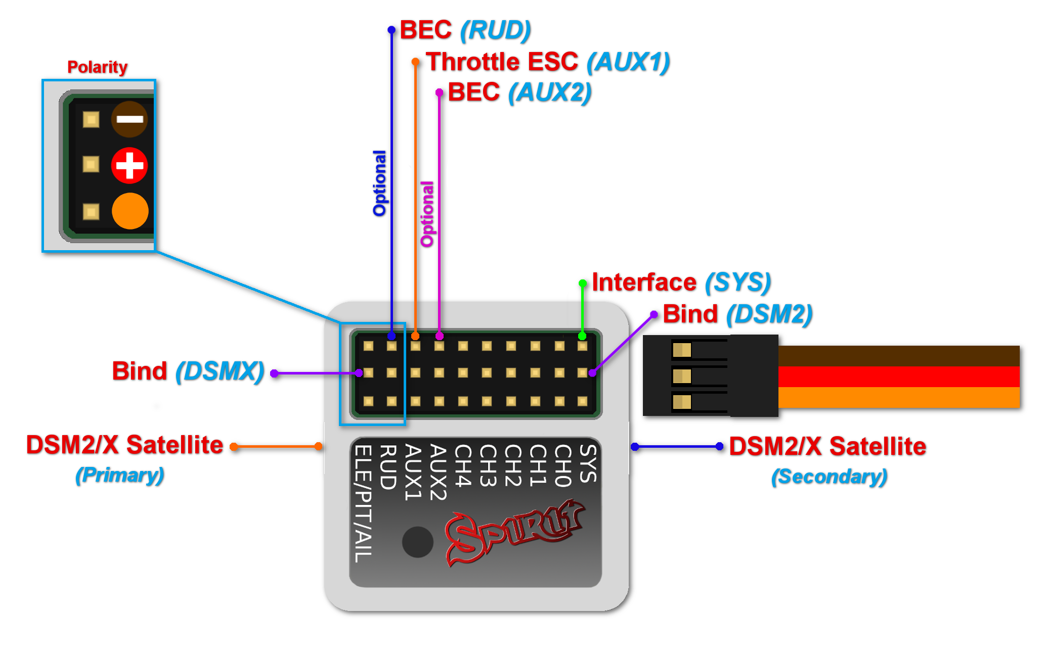
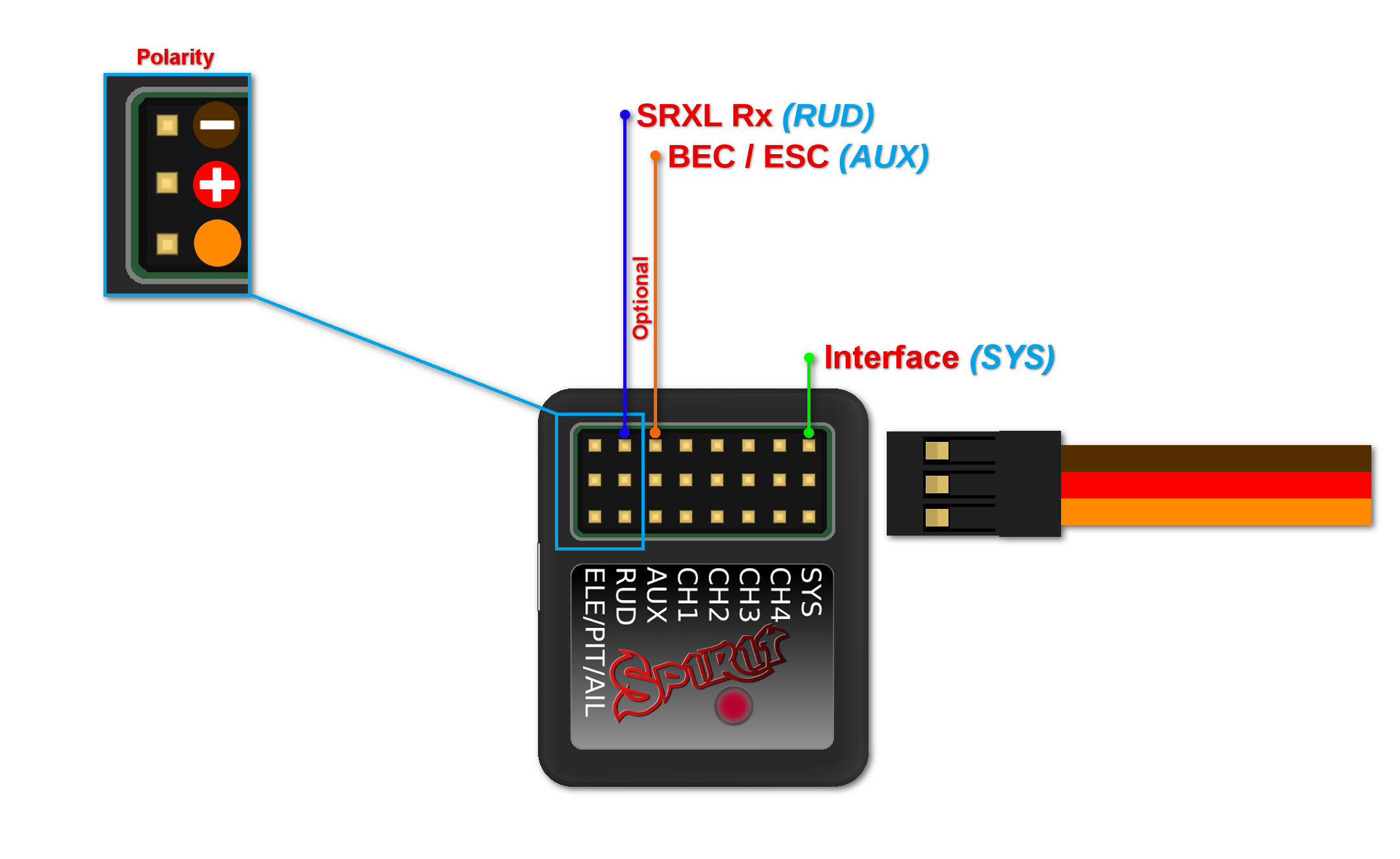
Pin layout of the JST-ZH(R) connectors is different from standard Servo connectors. BROWN (Middle) wire is GND pin. ORANGE wire is SIGNAL pin. RED wire is +5V (BEC voltage). By using JST-Servo cables you can connect a classic Servos and all Spirit peripherals to the μSpirit even with Servo connectors.
3.2 Spirit and Spirit Pro
All cables connected to the unit must be oriented so that the signal wire (ORANGE wire) is closer to the connector pin label, towards the center of the unit. This orients the negative (BROWN wire) toward the edge of the unit.
3.3 Spirit 2, Spirit RS, Spirit GT, Spirit GTR
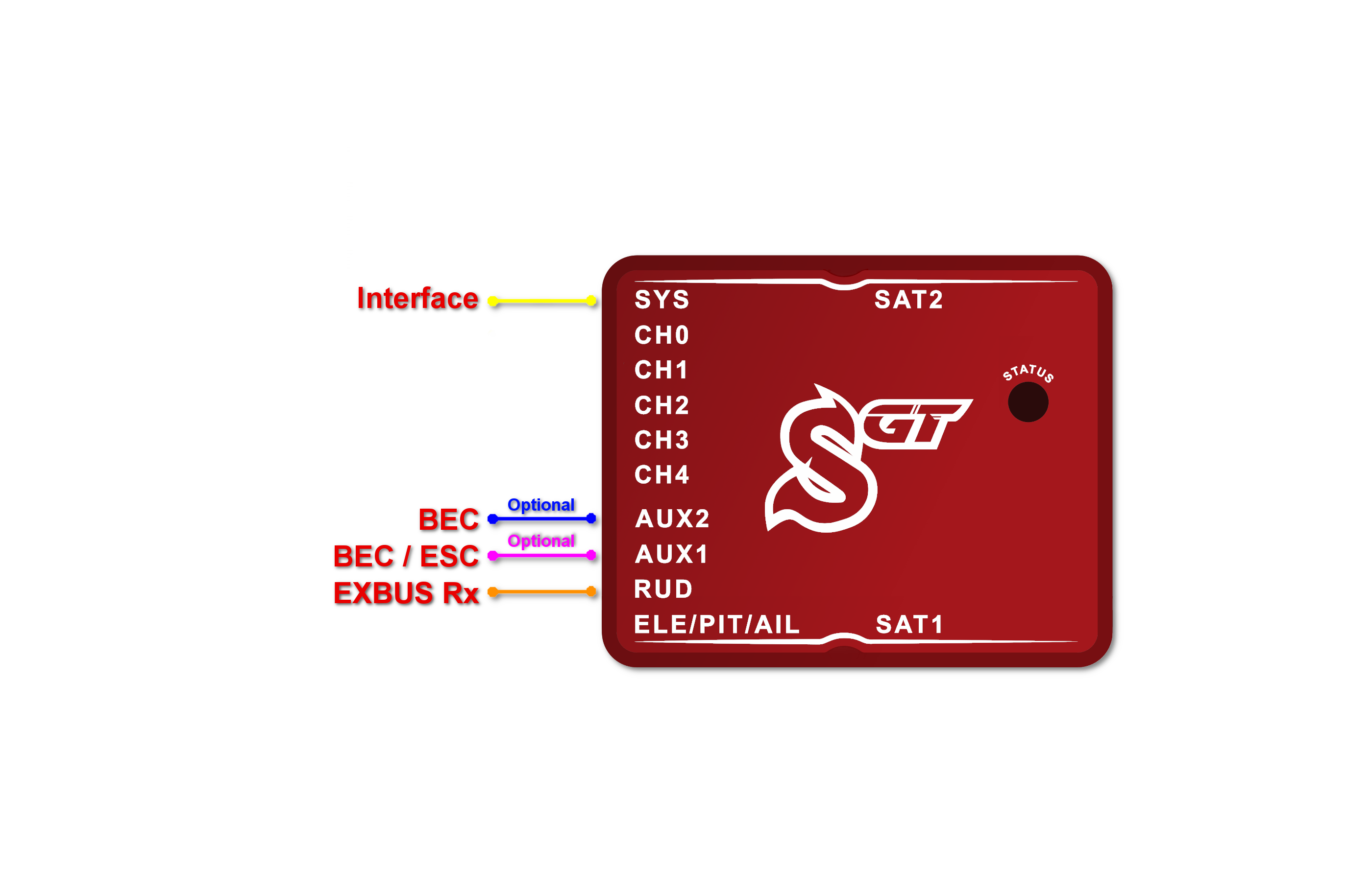
All cables connected to the unit must be oriented so that the signal wire (ORANGE wire) is at the top of the unit. This orients the negative (BROWN wire) at the bottom of the unit.
4 SERVOS WIRING
Spirit units have full support for all types of servos. Please proceed according the Setup Wizard in Spirit Settings software to see how to connect the servos properly.
Spirit is pre-programmed to 1520µs servo neutral impulse and 50Hz frequency – please ensure you have the correct servo parameters selected as specified by your servo manufacturer.
If the neutral impulse of your servo/s is different to the above, such as 760µs, do not connect this servo yet as it could be damaged.
Some connectors have non-standard dimensions that could interfere with neighboring connectors after plugging in the unit. As a solution, we recommend replacing these connectors with JR or Futaba type.
Never plug a connector for powering the unit into the SYS or ELE/PIT/AIL positions or you may risk damaging the unit.
| μSpirit |
| CH1 – Pitch / Aileron servo |
| CH2 – Elevator servo |
| CH3 – Aileron / Pitch servo |
| CH4 – Rudder servo / Rudder ESC |
| Spirit, Spirit 2, Spirit RS |
| CH1 – Pitch / Aileron servo |
| CH2 – Elevator servo |
| CH3 – Aileron / Pitch servo |
| CH4 – Rudder servo |
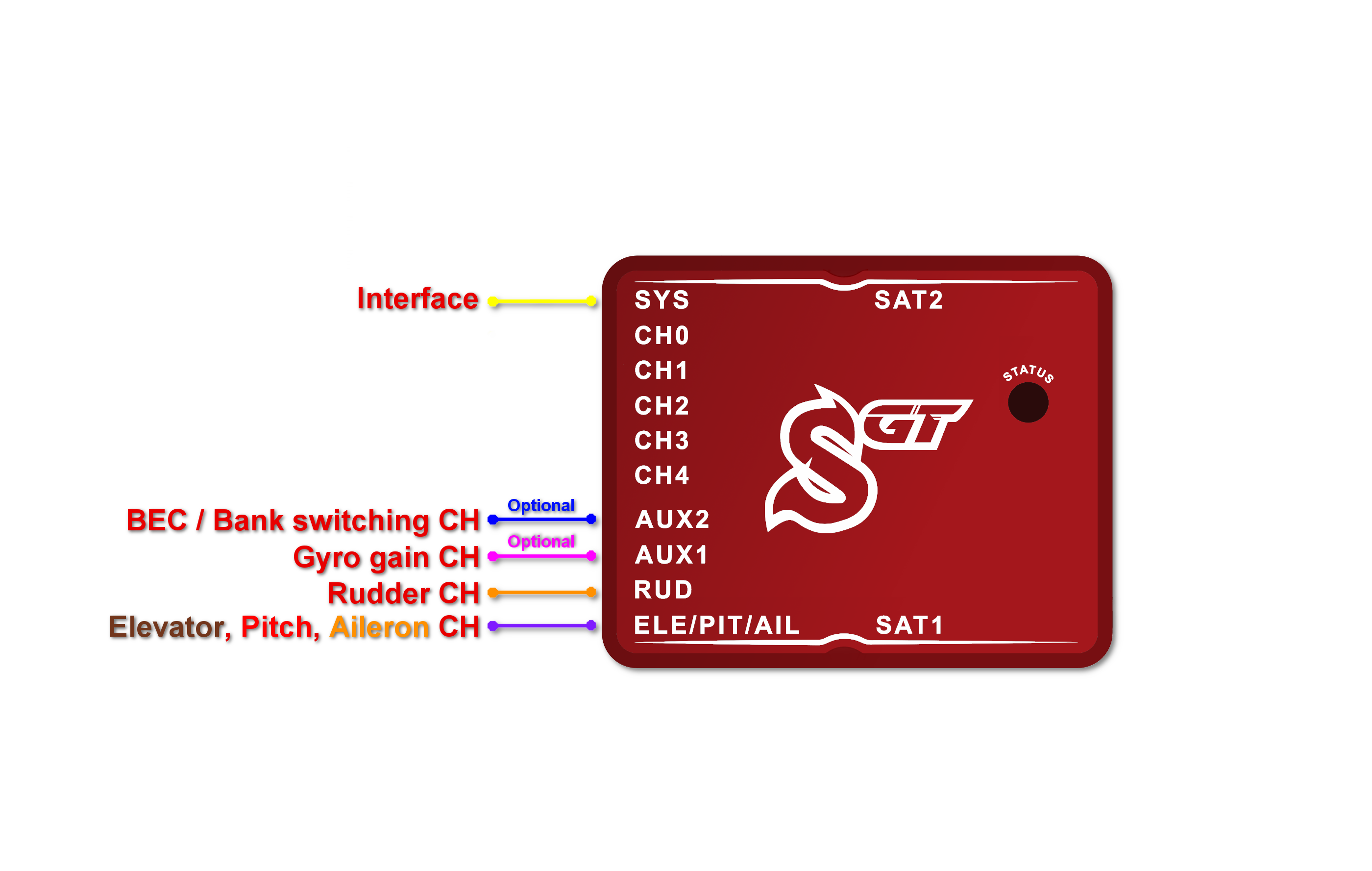
| Spirit Pro, Spirit GT, Spirit GTR |
| CH1 – Pitch / Aileron servo |
| CH2 – Elevator servo |
| CH3 – Aileron / Pitch servo |
| CH4 – Rudder servo |
| CH0 – auxiliary (optional) cyclic servo for CCPM 90 swashplate type. |
Servos at positions CH1 and CH3 are dependent on the Swashplate settings. Aileron servo on the model is mostly positioned on the right side while pitch on the left side.
5 ESC/MOTOR WIRING
Electronic Speed Controllers (ESCs) for electric motors or Throttle Servos for combustion motors can be connected in two ways:
- In the receiver - Throttle port (Failsafe is handled by receiver)
- In the Spirit unit - AUX (AUX1) port (Failsafe is handled by unit and/or additionally by receiver)
Wiring details for each receiver type are described always in the particular scheme - see next sections.
With Spektrum DSM2/X satellites throttle must be connected always to the unit.
By default Throttle output from the unit is disabled for all receiver types (except Spektrum DSM2/X). Assign Channel 1 in the General/Channels - Throttle.
In order to use Governor it is always required to use Throttle output from the unit.
Throttle frequency that can be configured in the unit can stay at default settings (60Hz). Only if Governor is used it is usefull to set as high frequency as possible. Recommended values are described in the Governor page.
5.1 Castle ESC
If Castle ESC is used, please configure following Throttle parameters in the General - Throttle/Governor window:
- Throttle Frequency: 60Hz.
- Throttle Range - Min.: 1060 us.
- Throttle Range - Max.: 1940 us.
All other ESCs should work well with default settings. If not, please use the Factory default.
5.2 Throttle Servo
For combustion helicopters it is required to set optimal travel range in order to prevent a binding. If the servo is connected in the unit, you can set absolute limits that can never be exceeded. These can be configured in the General - Throttle/Governor - Throttle Range.
It is also possible that Throttle Reverse will be necessary to get fully closed condition when Throttle Hold is engaged. This will change servo movement direction.
5.3 µSpirit and Rudder ESC/Motor
µSpirit unit has full support for motor driven tail rotors. These motors are usually driven by a dedicated ESC. To control the motor standard servo signal is used. Connect Rudder ESC at the CH4 port. In the Setup Wizard it is necessary to set Rudder - Control type to Motor.
Lastly make sure you will set Throttle range for this ESC. Please see description of the Rudder End-points in the Configuration/Limits tab section.
In order to turn off the Tail motor when Main motor is not running it is necessary to later assign the Throttle channel. See the Channels assignment in the Configuration/General - Channels section. This can be changed anytime after the basic configuration.
6 CONNECTION OF STANDARD RECEIVER (PWM)
μSpirit – receiver type: PWM
Spirit – receiver type: PWM
Spirit Pro – receiver type: PWM
Spirit 2– receiver type: PWM
Spirit GT– receiver type: PWM
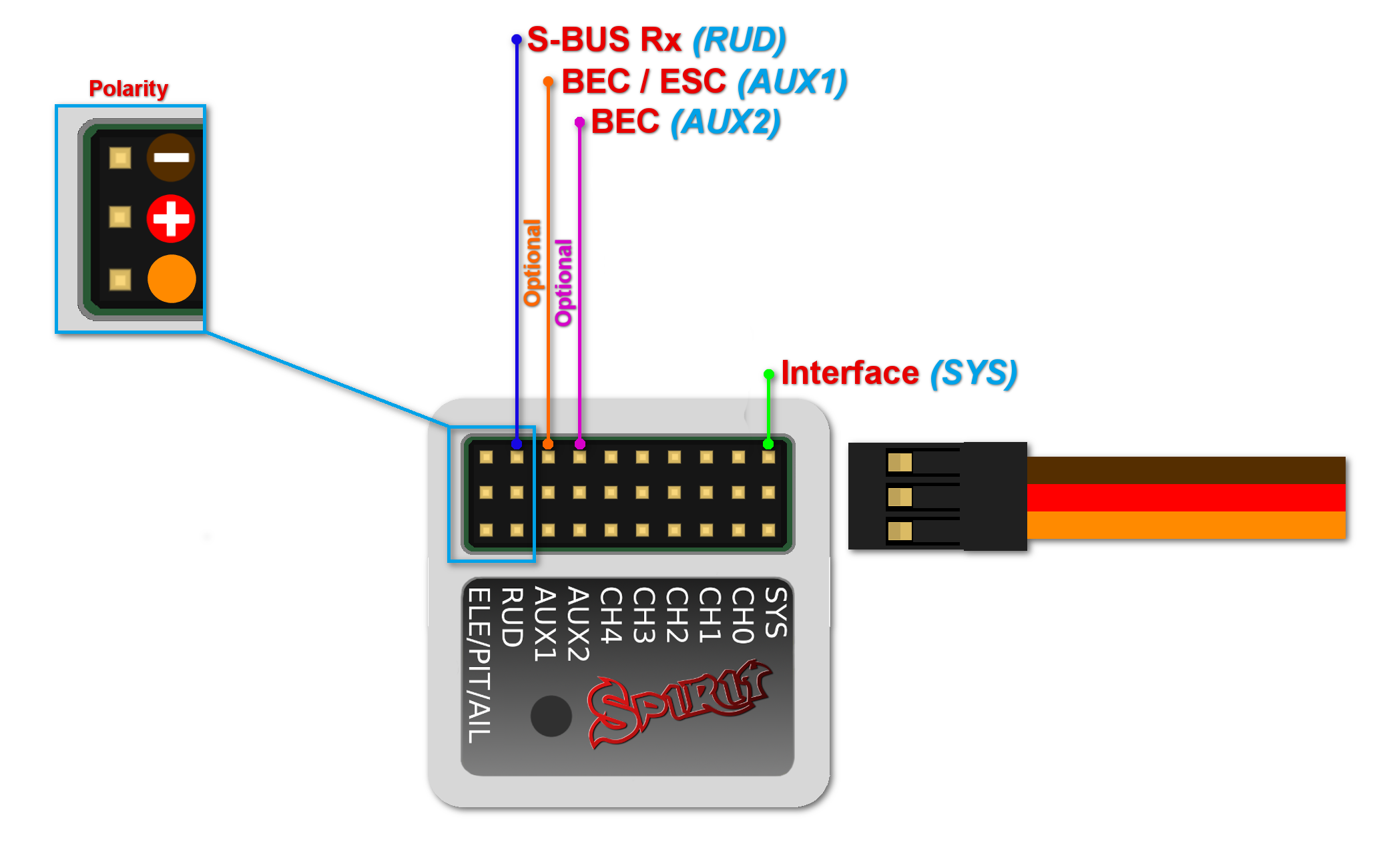
For standard receivers it is necessary to use two normal and one special cable. Three connectors from the special cable should be plugged into the receiver and the end of these cables to the unit.
The unit is powered by two cables from the receiver. These are connected to the AUX and RUD positions. The Throttle (ESC or Throttle servo) should be connected to the receiver.
The easiest way you can start is to connect a cable between the RUD port with Rudder output of the receiver. Then continue with the AUX port which should be connected to the Gyro Gain channel output of the receiver. Next, connect the Aileron, Elevator and Pitch channels. If you are not sure whether you have the correct output or not, you can plug in one servo and power the unit to verify that your connection is correct. This can be repeated for each servo. The Diagnostic tab in the software is very helpful too, because you can see whether the connection is correct even without connected servos.
For Spektrum receivers you can view the Spektrum PWM connection scheme.
Spirit 2, Spirit Pro, Spirit GT
The unit is able to control Bank Switching by 7th channel of the receiver. Connect the cable to the AUX2 port and allow Bank Switching in the software.
Never plug a connector for powering the unit to SYS or ELE/PIT/AIL ports.
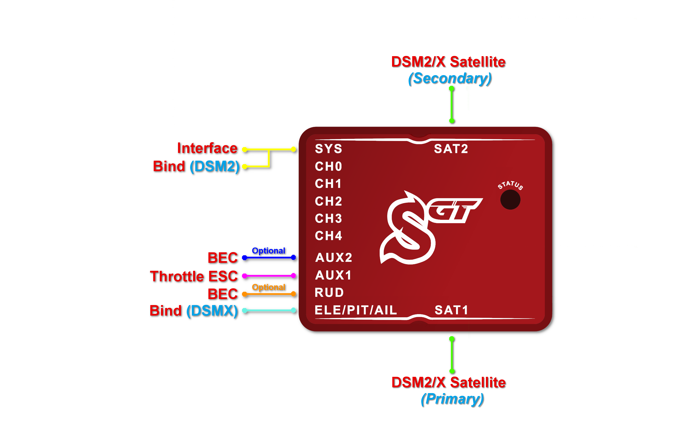
7 CONNECTION OF SPEKTRUM DSM2/X SATELLITE
μSpirit – receiver type: Spektrum DSM2/X
Spirit – receiver type: Spektrum DSM2/X
Spirit Pro – receiver type: Spektrum DSM2/X
Spirit 2 – receiver type: Spektrum DSM2/X
Spirit GT– receiver type: Spektrum DSM2/X
Connection to a BEC is optional. If the model is powered by an external BEC, this must be connected to the RUD port. Also the power lead from the ESCs internal BEC must be disconnected.
Spirit
A second satellite can be connected, but this can only be achieved via a special adapter connected to the RUD port. This adapter can be purchased separately. Before satellites can be used they must be bound to your transmitter, taking into account any failsafes that need to be set. To use both, two satellites and an external BEC, be sure to use a Y-harness made from large gauge wire to supply the high current that is needed.
Spirit Pro, Spirit 2, Spirit GT
You can connect two satellites directly to the unit. If you want to use only one satellite, you have to use the Primary (SAT-1) connector.
To bind the satellites, insert a bind plug in the SYS port for DSM2 satellites or the ELE/PIT/AIL port for DSMX satellites. Power cycling the Spirit start the bind process. Once successfully bound, the STATUS LED will go out and the satellite LED will come on.
If the second satellite fails to bind, swap the satellites and repeat the bind process.
Be sure Receiver type in the software is configured to Spektrum DSM2/X otherwise binding process will not work. Never plug a connector for powering the unit to SYS or ELE/PIT/AIL positions.
7.1 Spektrum Multi Adapter
Spektrum Multi Adapter allows to connect additional 2 Spektrum DSM2/X satellites.
It is suitable for all Spirit units and is recommended when using GeoLink module and/or ESC telemetry that is using a satellite ports. Before usage please bind satellites that are intended to be connected at the adapter through primary and secondary ports.
Servo cable: RUD port
Orange wire: AIL pin
Spirit
With this adapter it is possible to connect up to 3x Spektrum satellites at the same time.
Spirit 2, Spirit Pro, Spirit GT
With this adapter it is possible to connect up to 4x Spektrum satellites at the same time.
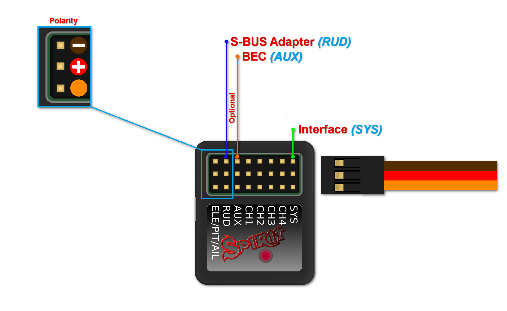
8 CONNECTION OF FUTABA S-BUS RECEIVER
μSpirit – receiver type: Futaba S-BUS
Spirit – receiver type: Futaba S-BUS
Spirit Pro – receiver type: Futaba S-BUS
Spirit 2 – receiver type: Futaba S-BUS
Spirit GT– receiver type: Futaba S-BUS
Spirit
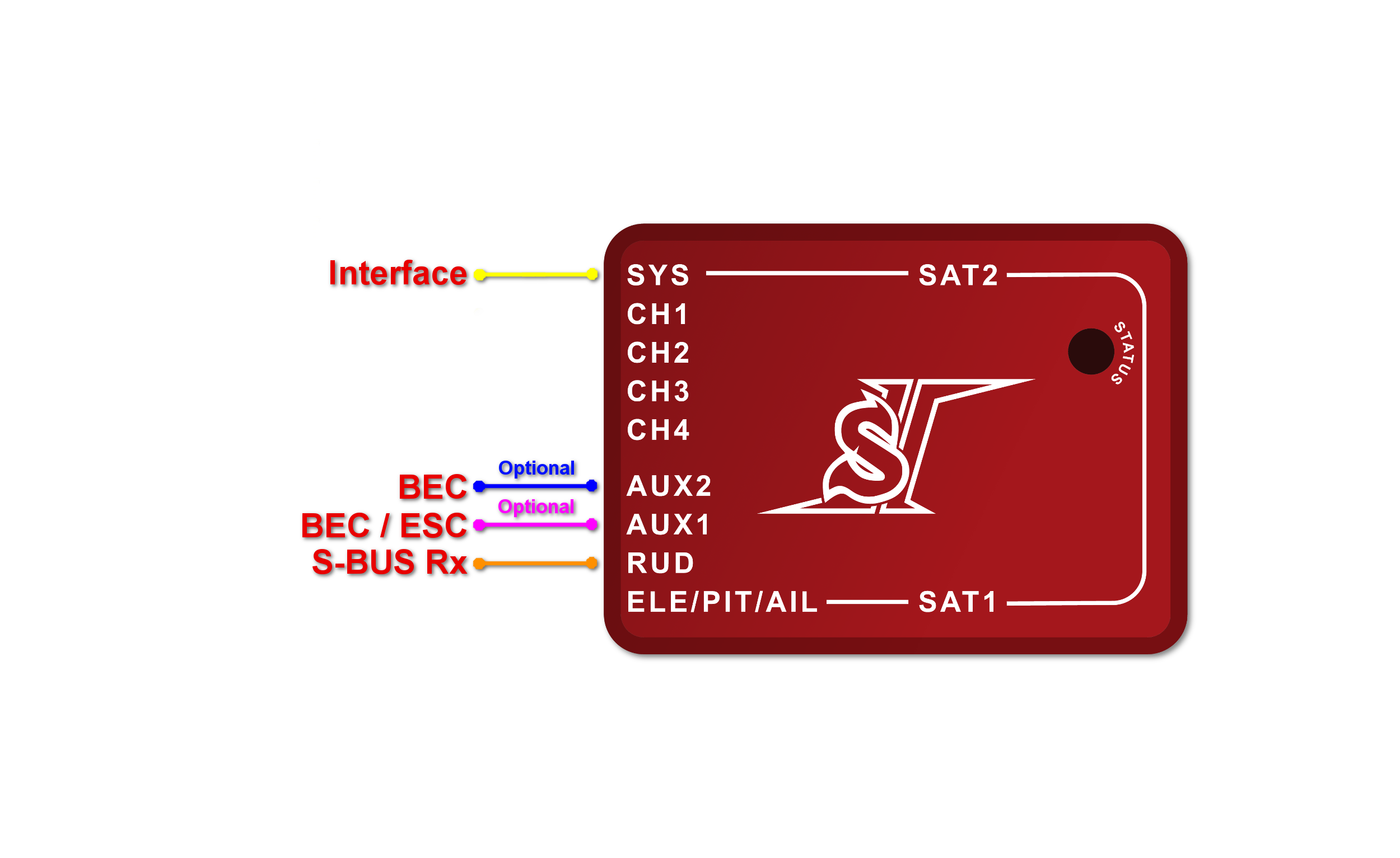
When using S-BUS it is necessary to use an inverter that replaces the cable between the receiver and the Spirit unit's RUD port. The inverter cable - called SBUS Adapter - can be purchased separately. The SBUS Adapter has to be connected in the way, that longer end is directed to the unit and shorter to the receiver. This apply for both Futaba and FrSky receivers.
μSpirit, Spirit Pro, Spirit 2, Spirit GT
Connect the receiver with the unit by normal patch cable to the RUD port. You can use cable that is included in the package.
Connection to a BEC is optional. For models of 500 size and larger it is recommended to use dual power supply cables due to the increased power consumption. That means besides the S-BUS cable, an additional power supply cable should be connected to the AUX port.
When using this type of receiver you can connect the throttle cable directly to the receiver. Alternatively, you can assign the throttle channel in the software and use the AUX as throttle output from the unit.
Never plug a connector for powering the unit to SYS or ELE/PIT/AIL ports.
9 CONNECTION OF PPM RECEIVER
μSpirit – receiver type: PPM
Spirit – receiver type: PPM
Spirit Pro – receiver type: PPM
Spirit 2 – receiver type: PPM
Spirit GT– receiver type: PPM
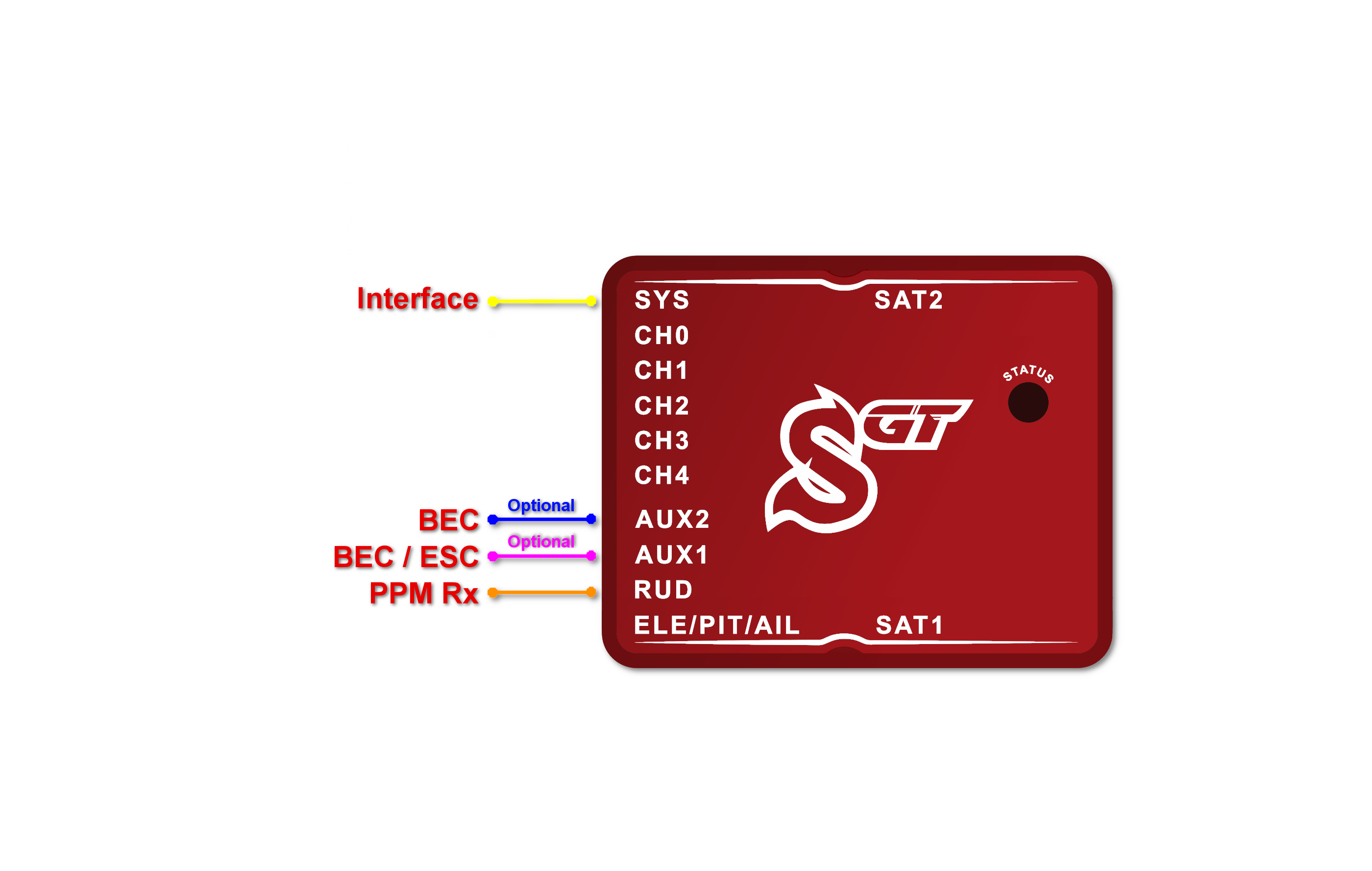
Connection to a BEC is optional. For models of 500 size and larger it is recommended to use dual power supply cables due to the increased power consumption. That means besides the communication cable, an additional power supply cable should be connected to the AUX port.
When using this type of receiver you can connect the throttle cable directly to the receiver. Alternatively, you can assign the throttle channel in the software and use the AUX as throttle output from the unit.
Never plug a connector for powering the unit to SYS or ELE/PIT/AIL ports.
Futaba pilots with PPM receiver such as R6107SP will need to reconfigure channels according Futaba PPM page.
10 CONNECTION OF JETI EX BUS RECEIVER
μSpirit – receiver type: Jeti EX Bus
Spirit – receiver type: Jeti EX Bus
Spirit Pro – receiver type: Jeti EX Bus
Spirit 2 – receiver type: Jeti EX Bus
Spirit GT– receiver type: Jeti EX Bus
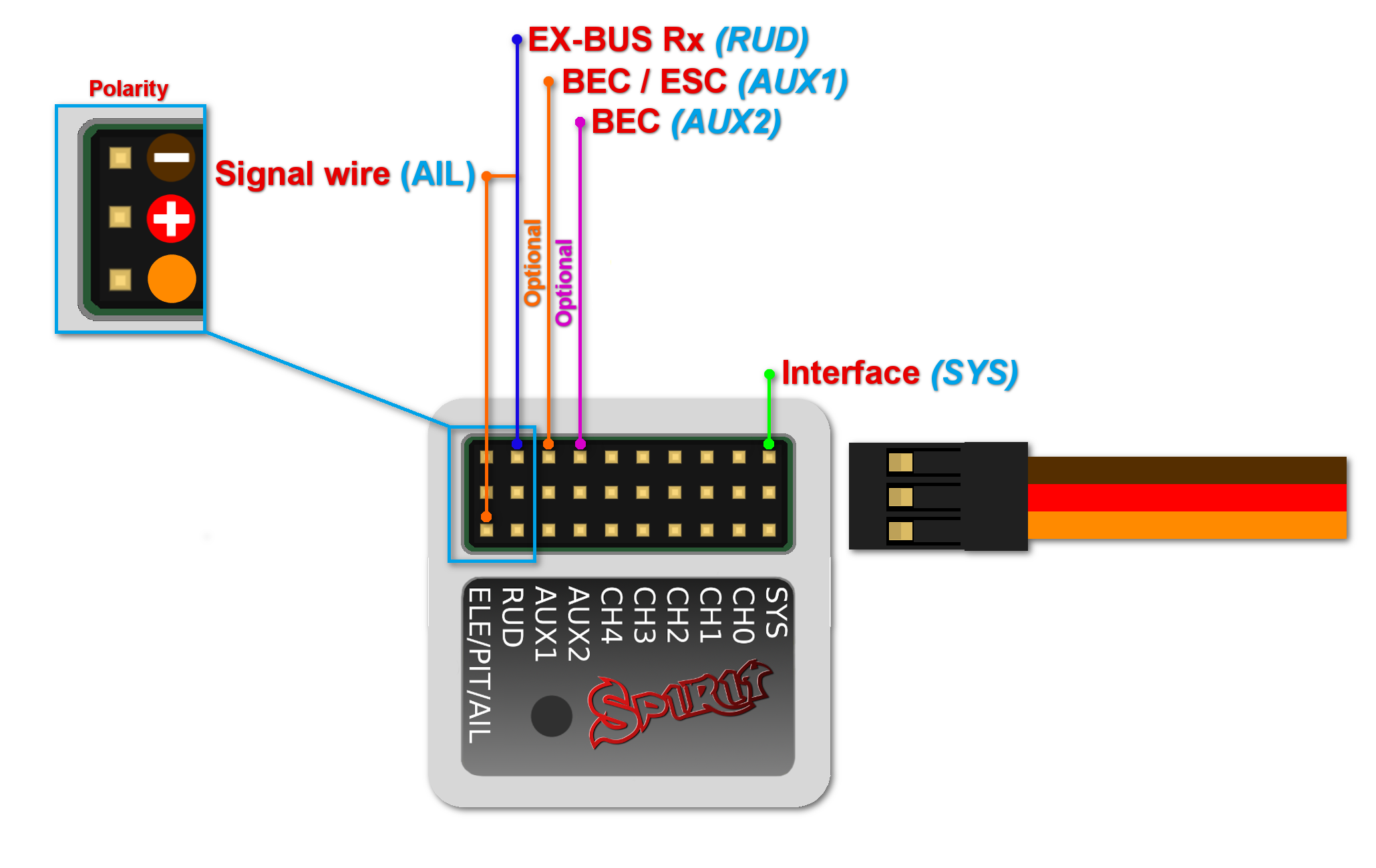
This connection type now supports the new integration with JETI Model transmitters. You can now fully configure the Spirit unit remotely through the JETI Model transmitter.
Remember to configure the receiver type through the software or the integration will not work. Also, it is necessary to download Spirit.bin file from the website. Move the file to the Devices directory in the SD card of your transmitter.
For futher instructions please check the Jeti Integration page.
Connection to a BEC is optional. For models of 500 size and larger it is recommended to use dual power supply cables due to the increased power consumption. That means besides the EX Bus cable, an additional power supply cable should be connected to the AUX port.
When using this type of receiver you can connect the throttle cable directly to the receiver. Alternatively, you can assign the throttle channel in the software and use the AUX as throttle output from the unit.
A special cable is needed to enable this communication. Signal wire (Orange) is connected to the AIL pin, while power wires (Red and Brown) are connected to the RUD port in the unit. For JETI REX receivers, end of the special cable is connected to the EX1 or EX2 (depending on the receiver configuration). For EX receivers, please use EXT port.
Never plug a connector for powering the unit to SYS or ELE/PIT/AIL ports.
11 CONNECTION OF SRXL/SUMD RECEIVER
μSpirit – receiver type: SRXL/SUMD
Spirit – receiver type: SRXL/SUMD
Spirit Pro – receiver type: SRXL/SUMD
Spirit 2 – receiver type: SRXL/SUMD
Spirit GT– receiver type: SRXL/SUMD
Connection to a BEC is optional. For models of 500 size and larger it is recommended to use dual power supply cables due to the increased power consumption. That means besides the communication cable, an additional power supply cable should be connected to the AUX port. This protocol family can work with a wide range of receivers. Thus you can use Multiplex SRXL, BeastX SRXL, Graupner SUMD, Jeti UDI, Spektrum SRXL, JR X-Bus (mode B) and more.
When using this type of receiver you can connect the throttle cable directly to the receiver. Alternatively, you can assign the throttle channel in the software and use the AUX as throttle output from the unit.
Never plug a connector for powering the unit to SYS or ELE/PIT/AIL ports.
12 CONNECTION OF FRSKY F.PORT RECEIVER
Spirit GT– receiver type: FrSky F.Port
This protocol is supported by the most FrSky ACCST receivers. Presently F.PORT 1 generation is fully supported. It allows to carry channel, telemetry and integration data at the same time. Only Spirit GT units have support for this protocol. More details can be found at the FrSky FPort page.
Connection to a BEC is optional. For models of 500 size and larger it is recommended to use dual power supply cables due to the increased power consumption. That means besides the communication cable, an additional power supply cable should be connected to the AUX port.
When using this type of receiver you can connect the throttle cable directly to the receiver. Alternatively, you can assign the throttle channel in the software and use the AUX as throttle output from the unit.
Never plug a connector for powering the unit to SYS or ELE/PIT/AIL ports.


