Difference between revisions of "GeoLink Mounting/ru"
(Created page with "Идеальное место размещение модуля GeoLink - хвостовая балка. Обычно это наилучшая позиция для дост...") |
(Updating to match new version of source page) |
||
| (47 intermediate revisions by 2 users not shown) | |||
| Line 5: | Line 5: | ||
Пожалуйста, обратите особое внимание и тщательно выполните следующие шаги. | Пожалуйста, обратите особое внимание и тщательно выполните следующие шаги. | ||
| − | == | + | == Mounting at the helicopter == |
Модуль должен монтироваться строго горизонтально так, чтобы логотип GeoLink находился сверху. Вы можете выбрать одну из двух позиций: | Модуль должен монтироваться строго горизонтально так, чтобы логотип GeoLink находился сверху. Вы можете выбрать одну из двух позиций: | ||
| Line 16: | Line 16: | ||
=== Где размещать === | === Где размещать === | ||
| − | + | GeoLink module should be mounted ideally at the TAIL BOOM. This is usually the best position for achieving optimal performance. | |
| + | Optimal position should meet the following: | ||
| + | * It is at least 5cm far from a rigid conductive parts such as carbon frame or bolts | ||
| + | * It is at least 5cm far from any electronics (especially servos) | ||
| + | * It is at least 8cm far from an electric motor | ||
| + | * It is at least 30cm far from any magnet (especially canopy magnetic mounts) | ||
| + | * It has clear sky visibility | ||
| + | * Is horizontally aligned as close as possible | ||
| − | + | Choose a position which is not too far, so that provided cable is long enough. Placing module too far at the boom could lead to bad Center of Gravity of the model. | |
| − | + | ||
| − | + | ||
| − | + | ||
| − | + | ||
| − | + | ||
| − | + | === Как крепить === | |
| − | + | Установка модуля обычно выполняется с помощью двухстороннего скотча из комплекта. Скотч держит очень крепко и достаточно будет всего двух кусочков. | |
| − | + | Некоторые вертолеты имеют балку более сложной формы ,чем просто труба. В этом случае есть вероятность, что вам придется потратить больше времени, чтобы установить модуль. | |
| − | + | При желании вы можете использовать сторонний крепеж для модулей GPS. | |
| − | + | ||
| − | + | ||
<br/> | <br/> | ||
| − | {{Quote|'''Never mount GeoLink directly | + | {{Quote|'''Never mount GeoLink directly at a thick metallic parts, near a motor or any servo.'''}} |
| + | <p></p> | ||
| + | {{Quote|'''Не закрывайте разъем Geolink скотчем или клеем. Отверстие разъема используется для определения давления и высоты.'''}} | ||
<br/> | <br/> | ||
[[File:geolink-horizontal.jpg|thumb|center]] | [[File:geolink-horizontal.jpg|thumb|center]] | ||
| − | <center>'' | + | <center>''Пример:'' Расположение '''Горизонтально (0°)''' . Основной ротор слева.</center> |
<br/> | <br/> | ||
| − | {{Info|[[File:info.png]] | + | {{Info|[[File:info.png]] Каждый электронная прибор, имеющий антенны, тщательно проектируется с учетом согласующего сопротивления антенн. Сопротивление антенны - это электрическое свойство, которое непосредственно определяет характеристики антенны. Сопротивление антенны мгновенно меняется если рядом с ней оказываются какие-либо детали. Поскольку часть платы действует как антенна GPS, любое изменение рядом с печатной платой или на ней, даже винты, имеет заметное влияние. Таким образом, мы настоятельно не рекомендуем делать какие-либо изменения в модуле GeoLink.}} |
| − | === | + | === Крепление на скотч из комплекта === |
| − | '''1. Take the first piece of tape and | + | '''1. Take the first piece of tape and put it approximately in the middle.''' |
[[File:geolink-mounting-1.jpg|500px|center]] | [[File:geolink-mounting-1.jpg|500px|center]] | ||
| − | ''' | + | '''Прикрепите модуль к хвостовой балке.''' |
[[File:geolink-mounting-2.jpg|500px|center]] | [[File:geolink-mounting-2.jpg|500px|center]] | ||
| − | ''' | + | '''Разрежьте вторую часть скотча.''' |
[[File:geolink-mounting-3.jpg|500px|center]] | [[File:geolink-mounting-3.jpg|500px|center]] | ||
| − | ''' | + | '''Удерживая сложенную ленту двумя пальцами, вставьте ее между модулем и балкой для создания опоры с двух сторон. Пальцем или подходящим инструментом попробуйте вставить обе части поглубже, чтобы модуль держался надежнее.''' |
[[File:geolink-mounting-4.jpg|500px|center]] [[File:geolink-mounting-5.jpg|500px|center]] | [[File:geolink-mounting-4.jpg|500px|center]] [[File:geolink-mounting-5.jpg|500px|center]] | ||
<br/> | <br/> | ||
| − | {{Quote|'''The tape will shortly adhere | + | {{Quote|'''The tape will shortly adhere at the surface tightly and can't be reused anymore.'''}} |
<br/> | <br/> | ||
| − | === | + | === Демонтаж === |
| − | + | В некоторых случаях может потребоваться снять GeoLink с модели, например, во время ремонта. При использовании двухстороннего скотча необходимо соблюдать особую осторожность! | |
| − | ''' | + | '''Всегда старайтесь сначала оторвать двусторонний скотч, а не сам модуль'''. Потом, осторожно вращайте модуль, пока не отлипнет двухсторонний скотч. |
<br/> | <br/> | ||
| − | {{Quote|''' | + | {{Quote|'''Никогда не тяните модуль при установке на двусторонний скотч! Есть риск погнуть или сломать пластиковый корпус.'''}} |
<br/> | <br/> | ||
| − | === | + | === GeoLink v2 Laser === |
| − | + | Spirit GeoLink v2 module is equipped with additonal sensor for precise altitude measurement. It is used when model is flying around 1 meter or lower. | |
| + | It can perform a milimeter-range precise measurements and also detect obstacles. | ||
| + | The laser is used automatically if it has a clear sight to the ground. Optionally it can be covered - in this case this sensor is unused. | ||
| + | No changes are needed when laser is unused. | ||
| + | |||
| + | === Примеры монтажа === | ||
| + | |||
| + | Монтаж может быть выполнен и другими способами. Пожалуйста, посмотрите следующие фотографии. | ||
==== LYNX Oxy 2 ==== | ==== LYNX Oxy 2 ==== | ||
| Line 85: | Line 94: | ||
[[File:geolink-goblin.jpg|thumb|center|SAB Goblin 700]] [[File:geolink-goblin-2.jpg|thumb|center|SAB Goblin 700]] | [[File:geolink-goblin.jpg|thumb|center|SAB Goblin 700]] [[File:geolink-goblin-2.jpg|thumb|center|SAB Goblin 700]] | ||
| − | == | + | == Подключение == |
| − | + | Соединение осуществляется одним проводом с разъемами JST длиной 22 см, который идет в комплекте GeoLink. Более длинный провод допустим и будет доступен (для приобретения). Для самого GPS все же лучше без необходимости не подключать слишком длинные провода, поскольку они могут влиять на сигнал. | |
| − | + | ||
<br/> | <br/> | ||
| Line 94: | Line 102: | ||
|- | |- | ||
| style="width: 55%;"|'''μSpirit''' | | style="width: 55%;"|'''μSpirit''' | ||
| − | |''' | + | |'''Primary''' satellite port (SAT) |
|- | |- | ||
| style="width: 55%;"|'''Spirit''' | | style="width: 55%;"|'''Spirit''' | ||
| + | |'''Primary ''' порт сателлита | ||
| + | |- | ||
| + | | style="width: 55%;"|'''Spirit Aero''' | ||
|'''Primary''' satellite port | |'''Primary''' satellite port | ||
| + | |- | ||
| + | | style="width: 55%;"|'''Spirit 2''' | ||
| + | |'''Secondary''' satellite port (SAT2) | ||
| + | |- | ||
| + | | style="width: 55%;"|'''Spirit RS''' | ||
| + | |'''Secondary''' satellite port (SAT2) | ||
|- | |- | ||
| style="width: 55%;"|'''Spirit Pro''' | | style="width: 55%;"|'''Spirit Pro''' | ||
| − | |'''Secondary''' satellite port | + | | '''Secondary''' порт сателлита |
| + | |- | ||
| + | | style="width: 55%;"|'''Spirit GT''' | ||
| + | |'''Secondary''' satellite port (SAT2) | ||
| + | |- | ||
| + | | style="width: 55%;"|'''Spirit GTR''' | ||
| + | |'''Secondary''' satellite port (SAT2) | ||
|} | |} | ||
<br/> | <br/> | ||
| − | {{Info|[[File:info.png]] GeoLink | + | {{Info|[[File:info.png]] Разъемы провода GeoLink совместимы разъемами сателлитов Spektrum.}} |
[[File:geolink-wiring.jpg|500px|center]] | [[File:geolink-wiring.jpg|500px|center]] | ||
| − | <center> | + | <center>Подключение к Spirit Pro</center> |
| − | == | + | == Выверка == |
| − | + | Так как визуально установить модуль ровно не просто, GeoLink имеет встроенный цифровой уровень в программе настройки Spirit. Там вы можете посмотреть как выровнен модуль и скорректировать при необходимости. | |
[[File:GeoLink-Alignment.png|550px|center]] | [[File:GeoLink-Alignment.png|550px|center]] | ||
| − | === | + | === Процесс выверки === |
| − | + | Выверка может быть выполнена до монтажа или даже позже, при необходимости. | |
#Connect GeoLink and Spirit unit with provided cable (while GeoLink being not mounted yet). | #Connect GeoLink and Spirit unit with provided cable (while GeoLink being not mounted yet). | ||
| Line 125: | Line 148: | ||
#Open ''General tab - GeoLink module'' settings. | #Open ''General tab - GeoLink module'' settings. | ||
#Move to the ''Module tab'' there. | #Move to the ''Module tab'' there. | ||
| − | #Place GeoLink at a flat, aligned horizontal surface anywhere | + | #Place GeoLink at a flat, aligned horizontal surface anywhere at your model in order to get a precise reference. (for example the Spirit unit) |
#Click '''Set as zero (temporarily)''' button to reset angle of built-in protractor. | #Click '''Set as zero (temporarily)''' button to reset angle of built-in protractor. | ||
#Move GeoLink to a desired mounting position. | #Move GeoLink to a desired mounting position. | ||
| Line 135: | Line 158: | ||
{|style="width: 100%;color: white;" | {|style="width: 100%;color: white;" | ||
|- | |- | ||
| − | | style="width: 33%;"| [[GeoLink_Features|← | + | | style="width: 33%;"| [[GeoLink_Features/ru|← Функции]] |
| − | | style="width: 33%;text-align:center;"| [[#up|↑ | + | | style="width: 33%;text-align:center;"| [[#up|↑Вверх↑]] |
| − | | style="text-align:right;" | [[GeoLink_Configuration| | + | | style="text-align:right;" | [[GeoLink_Configuration/ru|Настройка →]] |
|} | |} | ||
---- | ---- | ||
</div> | </div> | ||
Latest revision as of 08:41, 6 September 2022
Правильный монтаж - залог надежной работы модуля. Если он выполнен неправильно, GeoLink не сможет обеспечить точность позиционирования или даже не смогут работать некоторые функции.
Пожалуйста, обратите особое внимание и тщательно выполните следующие шаги.
Contents
1 Mounting at the helicopter
Модуль должен монтироваться строго горизонтально так, чтобы логотип GeoLink находился сверху. Вы можете выбрать одну из двух позиций:
- Горизонтально (0 °) - разъем указывает на основной ротор
- Горизонтально (180 °) - разъем указывает на хвостовой ротор
Перед фактическим монтажом ознакомьтесь с разделом Выверка.
1.1 Где размещать
GeoLink module should be mounted ideally at the TAIL BOOM. This is usually the best position for achieving optimal performance. Optimal position should meet the following:
- It is at least 5cm far from a rigid conductive parts such as carbon frame or bolts
- It is at least 5cm far from any electronics (especially servos)
- It is at least 8cm far from an electric motor
- It is at least 30cm far from any magnet (especially canopy magnetic mounts)
- It has clear sky visibility
- Is horizontally aligned as close as possible
Choose a position which is not too far, so that provided cable is long enough. Placing module too far at the boom could lead to bad Center of Gravity of the model.
1.2 Как крепить
Установка модуля обычно выполняется с помощью двухстороннего скотча из комплекта. Скотч держит очень крепко и достаточно будет всего двух кусочков.
Некоторые вертолеты имеют балку более сложной формы ,чем просто труба. В этом случае есть вероятность, что вам придется потратить больше времени, чтобы установить модуль.
При желании вы можете использовать сторонний крепеж для модулей GPS.
Never mount GeoLink directly at a thick metallic parts, near a motor or any servo.
Не закрывайте разъем Geolink скотчем или клеем. Отверстие разъема используется для определения давления и высоты.
Каждый электронная прибор, имеющий антенны, тщательно проектируется с учетом согласующего сопротивления антенн. Сопротивление антенны - это электрическое свойство, которое непосредственно определяет характеристики антенны. Сопротивление антенны мгновенно меняется если рядом с ней оказываются какие-либо детали. Поскольку часть платы действует как антенна GPS, любое изменение рядом с печатной платой или на ней, даже винты, имеет заметное влияние. Таким образом, мы настоятельно не рекомендуем делать какие-либо изменения в модуле GeoLink.
1.3 Крепление на скотч из комплекта
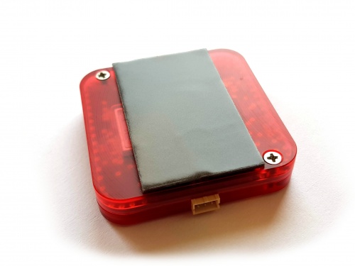
1. Take the first piece of tape and put it approximately in the middle.
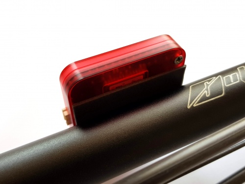
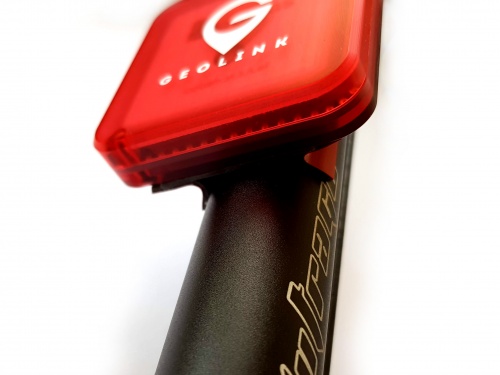
Прикрепите модуль к хвостовой балке.
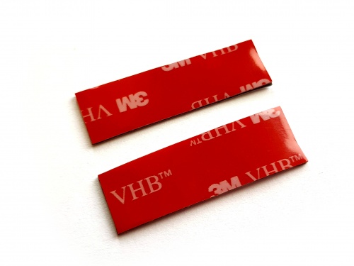
Разрежьте вторую часть скотча.
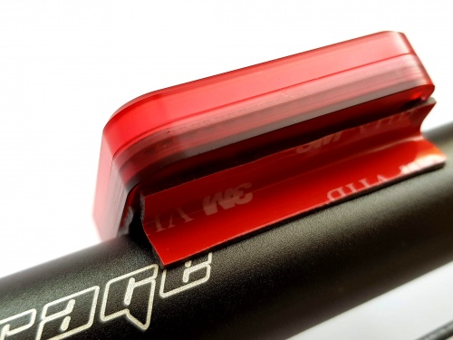
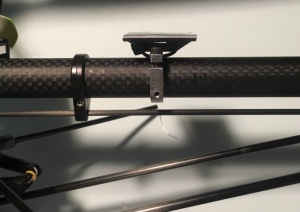
Удерживая сложенную ленту двумя пальцами, вставьте ее между модулем и балкой для создания опоры с двух сторон. Пальцем или подходящим инструментом попробуйте вставить обе части поглубже, чтобы модуль держался надежнее.
The tape will shortly adhere at the surface tightly and can't be reused anymore.
1.4 Демонтаж
В некоторых случаях может потребоваться снять GeoLink с модели, например, во время ремонта. При использовании двухстороннего скотча необходимо соблюдать особую осторожность!
Всегда старайтесь сначала оторвать двусторонний скотч, а не сам модуль. Потом, осторожно вращайте модуль, пока не отлипнет двухсторонний скотч.
Никогда не тяните модуль при установке на двусторонний скотч! Есть риск погнуть или сломать пластиковый корпус.
1.5 GeoLink v2 Laser
Spirit GeoLink v2 module is equipped with additonal sensor for precise altitude measurement. It is used when model is flying around 1 meter or lower. It can perform a milimeter-range precise measurements and also detect obstacles. The laser is used automatically if it has a clear sight to the ground. Optionally it can be covered - in this case this sensor is unused. No changes are needed when laser is unused.
1.6 Примеры монтажа
Монтаж может быть выполнен и другими способами. Пожалуйста, посмотрите следующие фотографии.
1.6.1 LYNX Oxy 2
1.6.2 KDS Chase 360
1.6.3 SAB Goblin 700
2 Подключение
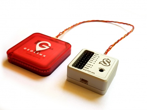
Соединение осуществляется одним проводом с разъемами JST длиной 22 см, который идет в комплекте GeoLink. Более длинный провод допустим и будет доступен (для приобретения). Для самого GPS все же лучше без необходимости не подключать слишком длинные провода, поскольку они могут влиять на сигнал.
μSpirit Primary satellite port (SAT) Spirit Primary порт сателлита Spirit Aero Primary satellite port Spirit 2 Secondary satellite port (SAT2) Spirit RS Secondary satellite port (SAT2) Spirit Pro Secondary порт сателлита Spirit GT Secondary satellite port (SAT2) Spirit GTR Secondary satellite port (SAT2)
Разъемы провода GeoLink совместимы разъемами сателлитов Spektrum.
3 Выверка
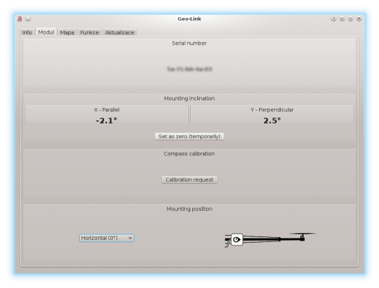
Так как визуально установить модуль ровно не просто, GeoLink имеет встроенный цифровой уровень в программе настройки Spirit. Там вы можете посмотреть как выровнен модуль и скорректировать при необходимости.
3.1 Процесс выверки
Выверка может быть выполнена до монтажа или даже позже, при необходимости.
- Connect GeoLink and Spirit unit with provided cable (while GeoLink being not mounted yet).
- Power up the Spirit unit.
- After initialization start the Spirit Settings software.
- Open General tab - GeoLink module settings.
- Move to the Module tab there.
- Place GeoLink at a flat, aligned horizontal surface anywhere at your model in order to get a precise reference. (for example the Spirit unit)
- Click Set as zero (temporarily) button to reset angle of built-in protractor.
- Move GeoLink to a desired mounting position.
- Mount it with provided double sided tape at position ideally with 0° deflection.

