Difference between revisions of "Spirit RPM Sensor"
| Line 35: | Line 35: | ||
Governor Settings</translate> == | Governor Settings</translate> == | ||
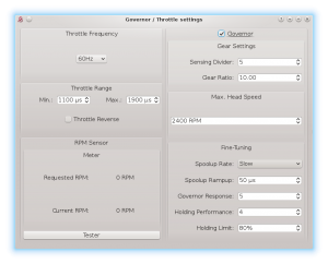
| − | <translate> | + | <translate>When sensor is connected you can optionally use Spirit Governor. |
| − | When sensor is connected | + | Please set the ''Sensor Divider'' parameter so that the value will represent count of the active magnets. |
Usually it is 1 or 2 magnets.</translate> | Usually it is 1 or 2 magnets.</translate> | ||
[[File:<translate><!--T:19--> | [[File:<translate><!--T:19--> | ||
Gov-divider.png</translate>|center|thumb]] | Gov-divider.png</translate>|center|thumb]] | ||
Revision as of 12:01, 23 November 2021
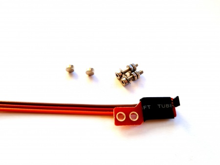
This sensor is HALL type which senses RPM by motion of the rotating magnets. Usually 1 - 2 neodymium magnets are mounted on the fan of combustion helicopters with a Nitro motor.
- Wire layout
- Orange wire: RPM Output Signal
- Red wire: Ground
- Brown wire: 3.3V - 15V
1 Wiring Example
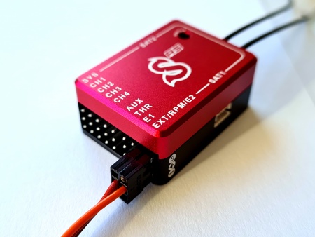
Powering Lead with Red and Brown wires can be plugged to any free port with a BEC voltage. Signal Lead with Orange wire must be plugged always at the middle Pin of the ELE/PIT/AIL port (Spirit 1, Spirit Pro, Spirit 2, Spirit GT) or EXT/RPM/E2 port (Spirit RS and Spirit GTR).
2 Magnet mounting
We highly recommend to orientate each magnet as Active for a proper operation. More magnets will result in a higher reading resolution thus increased readout precision.
3 Governor Settings
When sensor is connected you can optionally use Spirit Governor. Please set the Sensor Divider parameter so that the value will represent count of the active magnets. Usually it is 1 or 2 magnets.


