Difference between revisions of "Configuration/zh-hant"
(Created page with "集體間距助力器 (Pitch Pump Booster)") |
(Created page with "為了實現類似有副翼集體螺距的行為,您可以增加此值直到達到理想的感覺。 請記住,更高的數值對於模型上的電源和伺服器的要求...") |
||
| Line 594: | Line 594: | ||
例如,90的值將使升降旋轉到副翼。 對於具有多主槳的型號(例如三個主槳頭),我們建議使用此功能。 對於大多數的其他型號,我們建議使用零值。 | 例如,90的值將使升降旋轉到副翼。 對於具有多主槳的型號(例如三個主槳頭),我們建議使用此功能。 對於大多數的其他型號,我們建議使用零值。 | ||
| − | '''集體間距助力器 (Pitch Pump Booster)'''<br /> | + | '''集體間距助力器 (Pitch Pump Booster)'''<br />為了實現類似有副翼集體螺距的行為,您可以增加此值直到達到理想的感覺。 請記住,更高的數值對於模型上的電源和伺服器的要求更高。 |
'''Signal processing'''<br />This parameter is used for operation on models with extreme vibrations that can't be eliminated in any way. This should be enabled only in cases when is absolutely necessary, because flight performance could be affected. It should increase precision of flight and also the precision of rescue and stabilization modes. | '''Signal processing'''<br />This parameter is used for operation on models with extreme vibrations that can't be eliminated in any way. This should be enabled only in cases when is absolutely necessary, because flight performance could be affected. It should increase precision of flight and also the precision of rescue and stabilization modes. | ||
Revision as of 01:26, 26 May 2017
配置是使系統正確運行的重要的步驟之一。使用軟件執行配置是十分簡單和有效率的,同時也提供可調參數,包括更複習的參數。軟件提供簡易安裝精靈。 我們強烈推薦新手使用 安裝精靈,它將引導您從頭開始完成整個配置。
Contents
1 連接到電腦
在開始實際配置之前,有需要先從電腦USB插口連接到Spirit 裡。 這取決於你所使用的操作系統和 電腦, 連接後有可能須要安裝驅動程式。
Spirit Settings適用於以下操作系統:
- Microsoft Windows
- Apple OS X
- GNU/Linux
- FreeBSD
一旦連接並且完成驅動程序安裝後會有一個新的虛擬COM端口 這認該在軟件和裝置管理員裡中可見。
MICROSOFT WINDOWS
通過軟件安裝程序安裝驅動程序。 這個過程將在
以下部分講解。
APPLE MAC OS X
為了正確設置功能,請在以下網址下載並安裝驅動程序:
http://spirit-system.com/dl/driver/SiLabsUSBDriverDisk.dmg
GNU/LINUX & FreeBSD
沒有需要安裝。
1.1 WIFI-LINK
現在Wifi模塊可以和Spirit Settings進行連接。 它被稱為'Spirit Wifi-Link。 Wifi-Link 可以完全取代USB接口。 因此用戶可以無線地執行所有設置。 您可以在Wifi-Link頁面找到連接的描述。
2 與Spirit連接
如果您已將USB接口連接到電腦,接下來 將USB綫的另一端連接到Spirit FB的“SYS”插口。 Spirit FBL無法從USB電綫/ SYS插口取電 所以有需要從接收器,BEC或用外部電池供電 。 RUD和AUX插口可用於為Spirit FBL供電,如果使用BEC 或電池組,建議使用電壓3V至15V之間連接到這些端口 。中間的那條線必須是正電壓連接。
切勿插入供電的連接頭到SYS或ELE / PIT / AIL位置,否則陀螺儀可能會損壞。
3 軟件安裝
以下是支援平台的安裝說明。 配置軟件可在Spirit System網站上找到:[1]。
MICROSOFT WINDOWS
運行安裝程序並跟隨安裝精靈。
如果驅動程序尚未安裝,在安裝精靈裡有選項可以安裝。
安裝精靈將會帶領你安裝所有必要的步驟。
完成安裝後,配置軟件可以從桌面啟動或在
程序列表,稱為“Spirit Settings”。
APPLE MAC OS X
安裝下載的軟件,打開DMG文件,然後移動
到您的應用程序文件夾。 配置軟件可以從應用程序文件夾"Spirit-Settings"中啟動。
GNU/LINUX a FreeBSD
將所有文件從下載的文件解壓到例如您的主目錄或桌面。
配置軟件可以從新創建的目錄啟動“settings.sh”。
4 軟件啟動
一旦安裝了軟件,請確保您的Spirit設備通過USB連接到 SYS端口,通電並初始化(LED指示燈亮起),然後運行 你的電腦上的軟件。
從桌面或安裝目錄中啟動“Spirit Settings”。
設置軟件應在Spirit FBL初始化後啟動。 每當Spirit FBL被初始化(狀態LED亮起)並連接時,您就可以進行設置。 基於安全問題,飛行中的設置是不可能的。
WINDOWS上的問題
如果配置軟件無法檢測到有效的COM端口,可以嘗試一下
以管理員身份啟動軟件。
或者,檢查COM端口號。 如果端口號太高,請嘗試
將端口號(Silabs device)重新配置為例如COM1 - COM4。
對於筆記本電腦,請禁用任何USB節電功能。
MAC的問題
如果配置軟件無法檢測到USB接口,請確保安裝了[2]。
版本是否正確也非常重要,否則會導致系統不穩定。
5 軟件使用
在成功連接Spirit FBL後,所有配置功能應該可以更改。 如果沒有的話,請嘗試選擇另一個COM端口(在電腦端)或 嘗試重新啟動軟件,斷開Spirit FBL與電源的連接 再重新連接。
確保在Spirit FBL初始化後啟動軟件。
5.1 連接選項 (CONNECTION TAB)
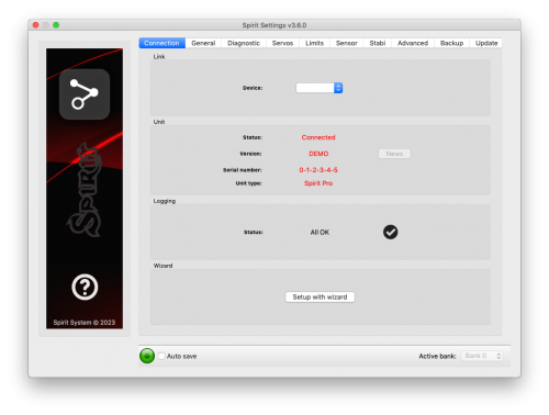
此選項表示連接的當前狀態,當前固件版本,顯示連接了Spirit FBL的序列號,並允許您更改COM端口。 另外還有一個引導你初始設置的設置精靈。
我們強烈建議你使用設置精靈,因為它將以最簡單的方式引導您完成基本設置。
5.2 一般選項 (GENERAL)
如果您已經使用設置精靈設置了本機,你可以在這裡進行其他操作 設置。 這裡還會顯示所有您在設置精靈裡設置的值。
無論任何時後更改參數,你所改變的值都會立即應用,但不會保存。 所以斷開電源之後,除非你手動保存了設置,否則所有未保存的更改將會消失。 請參閱備份選項(Backup tab)
位置 (Position)
選擇Spirit FBL在模型安裝的位置。
(請見第3節 - 安裝)
十字盤 (Swashplate)
選擇您的模型的十字盤類型。
在大多數情況下,它是“CCPM 120°或CCPM 120°(反方向)”。
接收器 (Receiver)
選擇您正在使用的接收器類型:
- PWM – 標準接收器。 (Standard receiver)
- PPM – 單線連接。(Single line connection)
- Spektrum DSM2/DSMX – DSM2或DSMX衛星。(DSM2 or DSMX satellite)
- Futaba S-BUS – 接收器通過SBUS連接。(Receiver connected via SBUS)
- Jeti EX Bus – 接收器通過EX Bus連接(用於 JETI model integration)。[Receiver connected via EX Bus]
- SRXL/SUMD – 接收器通過SRXL,SUMD,UDI連接。(Receiver connected via SRXL, SUMD, UDI)
飛行風格 (Flight style)
設置模型的飛行風格。
該參數用於控制和調整飛行員要求的螺距感度。
較低的參數值意味著模型將表現得更加一致, 模型比校上受控和感覺更像機械化。 更高的價值意味著更自然的行為。 相對上更敏捷的反應, 有點像有副翼一樣。
這參數不影響模型的穩定性。 大多數飛行員喜歡默認值為4。
通道分配 (Channels)
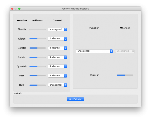
單擊通道分配 (Channels)的按鈕後,將會帶到你顯示通道分配的頁面。
您可以在此處為遙控器的通道進行功能上的分配。 通道的可用數量
取決於您的遙控器和接收機類型。 請謹記只可分配一個
通道到一個功能。
當分配了“油門” (Throttle) 的通道時,油門輸出將可從AUX裡獲得。
當Bank Switching (即是通過遙控器通道改變已設定的參數) 功能已分配到一個通道時,你將可以在該通道使用Bank Switching “(見第5.6章)”。
當尾舵增益(Gyro Gain)功能未被分配時,您可以直接從軟件裡的傳感選項(Sensor tab)更改尾舵增益
。 未分配的那個通道
將可作另一種方式使用,例如 Bank Switching切換。
故障保護 (Failsafe)
對於PPM,Futaba S-BUS,Spektrum DSM2 / X,Jeti EX Bus,SRXL / SUMD接收器類型
您可直接在Spirit FBL裡設置故障保護(Failsafe)。 通道值會在你單擊設置故障保護按鈕(Set failsafe button)後儲存。 如果信號
失去超過1秒鐘,它將在飛行中自動設置為該值。
使用其他接收器類型時,故障保護(Failsafe)可以在發射器或接收器中進行編程。
實時調整 (Realtime tuning)
如果你分配好參數“(P)”,您可以直接從遙控器裡更改設置。
您可以通過遙控器容易地更改通參數值(例如通過電位計)。
因此,其實您根本不需要配置軟件。 有一個遙控器就足夠了。
所以您只須更改遙控器的通道就即可以更改Spirit FBL參數值。 最大偏轉(Maximal deflection)將設置為參數的最大值,而最小偏轉(Minimal deflection)將設置為最小值。
實時參數調整(Realtime parameter tuning)是有優先的。 所以當您啟用時,從配置文件更改的值參數或Bank Switching的參數值將被忽略。
這個功能在沒跟軟件連接時才會啟用。 以防止碰撞的可能。 一旦軟件斷開連接,所選參數由遙控器裡的通道值配置。 在軟件再次啟動的情況下,它將用回其內存內實時調校(Realtime Tuning)時的參數值。
您可以使用此功能同時配置3個不同的參數和功能(例如救援模式)。
如果分配了功能“(F)”,當它的參數值等於1,這個功能將會打開。 振動分析功能(Vibration analysis function)允許您在飛行過程中測量振動。 稍後將在“診斷”選項 (Diagnostic tab)部分中會有介紹。
參數調整完成後,建議打開軟件並將設置保存到Spirit FBL。 然後取消分配了的參數,使其值不能再更改。
5.3 診斷選項 (DIAGNOSTIC TAB)
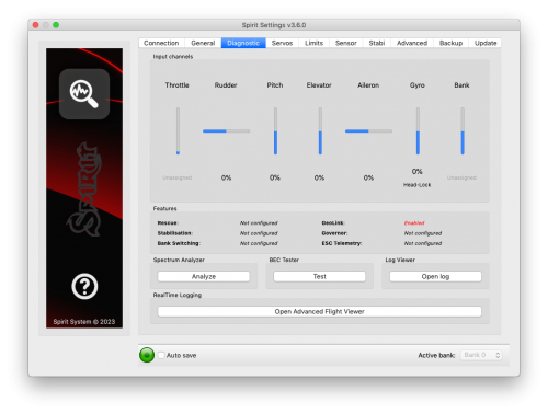
當你在上一個選項中設置完成,這時我們建議您請在遙控器裡作出任何調整和變更,使得遙控器控制與顯示中的系統有一樣的輸出。 簡單來說,每個遙控器的操縱桿中心點從來都不一樣的。 環境因數影響和磨損也可能產生影響令中心點常有波動。 另一個考慮因素是每個通道裡的最大值和最小值。 在這裡,您可以使用遙控器的舵機端點(Servo endpoint)來作調整。
其次,有必要檢查副翼(Aileron),升降(Elevator),俯仰(Pitch)尾舵等的數值。 這些通道必須以大約0%為中心。在初始化期間,Spirit FBL將會自動檢測中立位位置。 請不要在遙控器上使用輔助微調(subtrim)或微調(trim)功能,因為Spirit FBL會將其視為輸入命令。
確保所有輔助微調(Subtrims)和微調(Trims)都被歸零。還有建議設置最大值和最小值。
還有建議設置最大值和最小值。 測試所有通道的最小和最大值,如果這些值在診斷選項中不等於-100%和100%,遙控器裡的端點將需要調整。
如果有些通道在軟件中顯示通道中心有 振盪,則可能意味著遙控器裡的電位器幼磨損。 這時可以通過在“高級選項”(Advanced Tab)中增加死區(Stick Deadband)來補償
如果副翼(Aileron),升降(Elevator)或尾舵(Rudder)通道中的值在軟件裡以粗體顯示,那代表系統正在識別用於移動/旋轉對應的軸的命令。
要確定陀螺增益(Gyro Gain)和它的模式(Mode),您可以檢查在軟件裡的陀螺(Gyro)顯示。
振動分析 (Spectrum Analyser)
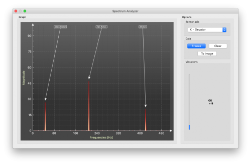
振動分析是用於測量模型振動量的工具。 它是一種診斷工具,主要是用來鎖定模型哪個旋轉部分會有過大的振動。 有了這些信息,您可以輕鬆識別和修復您模型的任何問題。
要檢查模型的狀態,您可以看到“振動”(Vibration)欄。 這顯示出所選那個軸的振動幅度。
振動分析可以在三個獨立的軸上測量振動:
- X - 升降軸 (Elevator axis)
- Y - 副翼軸 (Aileron axis)
- Z - 尾軸 (Rudder axis)
- In-Flight - 飛行振動播放器 (Flight vibration player)
這個圖實時顯示當前所選軸的頻率。 這使您能夠清楚看到所選軸上振動的頻率和幅度。
振動是根據多種因素傳輸到每個軸。 頻率和幅度取決於模型的結構。 通常的振動在Y軸(副翼)上是最高的,我們建議您在每次進行測量時檢查所有軸。 但請注意所有軸的振動不應超過50%。 在振動達到90%以上的情況下,該模型需要作出檢查。 當任何軸上的振動幅度超過90%,在飛行前先檢查模型, 雖然Spirit FBL對振動具有很高的抗振解讀力,但這些高振動可能會導致Spirit FBL裡的感應遲鈍,再甚者振動會令螺絲振掉出來導致模型機械故障。
振動級別:
- 振動到達50% - 振動在正常和可接受的水平 (Vibrations at a normal and acceptable level)
- 振動在50%和90%之間 - 提高振動水平 (Raised vibration levels)
- 振動超過90% - 過高的振動水平 (Extreme vibration levels)
除了總體振動水平不超過50%,任何特定頻率(峰值)不應超過50%。 任何高於這一級別都需要進一步檢查。
為了比較圖表,您可以使用“凍結”(Freeze)按鈕來在當前的實時圖表裡拍下來,並將顯示為子圖表(subgraph)。 可以使用“清除”(Clear)按鈕刪除此圖表。
可以保存圖表的。 使用“To image”按鈕,把當前圖形將被保存為jpg。
振動分析能夠檢測高達500Hz的振動頻率(轉速高達30,000 RPM的旋轉部件)。
測量程序
從模型中移除主槳和尾槳。
1.將模型放置在合適的柔軟表面(如地毯,草坪)上。
2.在主槳夾和尾槳夾上設置大約0°。
3.使用振動分析儀(伺服器不會動)。 將電機旋轉到常規飛行轉速。
4.在X,Y和Z軸之間切換,保存每個圖像。
5.檢查所有軸上的振動。
6.停止馬達。
識別振動
為了識別哪個部件或部件引起異常振動,這是需要知道最高峰的速度。 主槳轉速最低,尾槳轉速是主槳轉的4.5倍。 一般來說,模型尺寸越小,轉速越高
為了找出模型的哪一部分導致不必要的振動,將滑鼠移動到峰值並檢查轉速(RPM)。 主槳的轉速通常在1500至3500RPM的範圍內。 因此,如果速度在該範圍內,主齒輪,主軸,主軸軸承或主槳夾本身可能存在問題。
大多數的過度振動,不會常是跟尾部相關的。 要檢查是否有來自尾部的振動,您應該會找到比主槳頻率高4.5倍的頻率峰值。
一旦確定直升機的哪一部分引起不必要的振動,您可以逐漸撇除可疑組件的部件,重複測量過程,直到振動消失。 一旦振動水平下降到可接受的水平,您就可以找出可疑組件,並可以替換它。
使用裝有尾槳進行的測量會帶來一些安全隱患,並且還會顯示出更多的振動水平。
飛行中 - 飛行中的振動分析 (Vibration analysis from flight)
此功能允許您從飛行任何時刻記錄振動量。 通過選定的通道,您可以告訴設備何時應和如何記錄。 頻譜之後可以在“診斷/頻譜分析儀”(Diagnostic/Spectrum Analyzer)中的“飛行中” (In-Flight)選項中查看。 保存的振動譜將被存儲直到沒電。
如果您想在飛行中時進行振動測量,你可在一般/通道(General/Channels)中設置特殊功能。 只需在裡面分配功能“F:振動分析”(F: Vibration analysis) 到你想要測量的軸。 然後選擇一個用於激活這功能的遙控通道。
一旦該值等於1,就可以保存振動頻譜。 當功能值從0改為1時,該記錄會立刻保存。
在飛行過程中,您可以更改遙控器所選的開關狀態(例如雙向開關)。 著陸後,您可以將Spirit連接到軟件,並打開振動分析(Vibration analyzer)(選擇“飛行中”(In-Flight)軸顯示頻譜)。
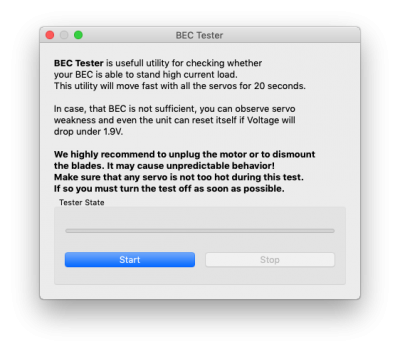
BEC測試 (BEC Tester)
這個測試用於確定您的Spirit,接收器和伺服器電源是否足夠。 這個測試目的是實現最大的電流值,並測試您的電源電壓不會下降到安全級別以下。
單擊“開始”(Start)按鈕開始測試。 20秒後應該會完成。
如果您發現任何問題,您的電源不足,請不要使用。 在這種情況下,您應使用可以准許電流較高的BEC。
日誌查看 (Log Viewer)
日誌用於在飛行過程中記錄事件。 如果發生問題,您不能立即知道或不明顯的時後,檢查日誌可以幫助您識別問題。
它會從Spirit啟動時記錄各種事件。 如果事件發生,您可以在日誌中看到一個新記錄,每10秒鐘報告一次日誌。 當您點擊“打開日誌”(Open log)按鈕時,您可以看到當前的日誌,其中包含上一次飛行時的所有事件。 當電源斷開時,日誌會被清除。
在飛行過程中出現重大問題的時後 20px,日誌將永久保存到本機的內存中,並保留在該位置,直到日誌打開為止。 如果日誌已保存,您會看到顯示“從先前航班登錄可用!”(Log from previous flight is available!) 的消息,並且可以打開發生問題時的日誌。 例如,當信號丟失或電源出現故障時,您可以在日誌中找到該問題。 發生主要問題的第一次總是會保存的。 如果沒有打開,則不會被較新的覆蓋。 在這種狀態下,用戶在Spirit初始化過程中也會在循環螺距上下動來通知你有新問題 – 升降(Elevator)伺服器將會改變其移動方向。
日誌可以包含以下事件:
- 該模型狀況良好。 Spirit沒有任何問題。 (The model is in good condition. The unit did not recognize any problems.)
-
- 傳感器校準成功。 (Sensor calibration was successful.)
-
- 定速實現了所需的轉速,並在使用定速。 (Governor achieved requested RPM and is active from this moment.)
-
![]() 循環開啟: (Cyclic Ring Activated:)
循環開啟: (Cyclic Ring Activated:)
- 循環螺距達到其最大攻角。 這表明模型無法根據需要進行所需的校正。 在大多數情況下,這是沒太關係的。 但是循環(Cyclic Ring)參數值可能太低,並且模型不能按照副翼(Aileron)/升降(Elevator)軸中預期的移動速度。 或者,可以配置了太高的轉速值。在快速飛行中(Fast Forward Flight),模型可能會快速俯仰。 我們建議改變一下機械可許下的參數值。 (Cyclic achieved its maximum tilt angle. This indicates the model was unable to do the desired correction as necessary. In most cases it is not relevant. But it is possible that the value of the Cyclic Ring parameter is too low and the model can't rotate as fast as intended in the aileron/elevator axes. Alternatively, a too high value for rotational speed could be configured. It is also possible that in fast forward flight the model can pitch-up rapidly. We recommend to set this parameter as high as mechanically possible.)
-
- 尾舵伺服器達到其配置極限。 當這個事件發生在飛行之前或之後,這不是問題。 如果在飛行過程中看到這一點,則說明尾舵沒有正常運行。 在大多數情況下,在飛行過程中可見尾舵反應不佳或控不住尾舵(Blow out)。 如果模型設置正確,那麼可能是由於尾舵伺服器太慢,如尾槳太短或者主轉速太低(Headspeed too load)。 還有可能是機械問題或尾舵限制不足。 (The rudder servo reached its configured limit. When this event occurs before or after a flight it is not a problem. If you see this during flight it indicates that the rudder did not operate correctly. In most cases it is visible during flight as poor rudder response or “blow out”. If the model is set up correctly then it could be due to low rudder efficiency such as the tail blades being too short or headspeed too low. There is also the possibility of a mechanical issue or with the rudder limits being inadequate.)
-
![]() 轉速傳感器數據太嘈雜: (RPM Sensor data are too noisy:)
轉速傳感器數據太嘈雜: (RPM Sensor data are too noisy:)
- 轉速讀數非常不穩定,轉速超過+/- 100 RPM。 傳感器的數據不可用於定速。 要使用額外的屏蔽和安裝鐵環(Ferite rings)。 在專家設置(Expert Settings)中增加轉速傳感器雜信過濾參數值。 (RPM readout is very unstable and are oscilating more than +/- 100 RPM. Data from the sensor are unusable for the Governor. Use additional shielding and mount a ferite rings. Increase value of the RPM Sensor filter parameter in the Expert settings.)
-
![]() 接收裡有一幀是錯誤的: (Received Frame was Corrupted:)
接收裡有一幀是錯誤的: (Received Frame was Corrupted:)
- 接收裡有一幀是不可用的,它將被忽略。 在大多數情況下,它是沒有任何問題的。但如果事件發生頻密,則接收機之間的連接可能出錯或存在過多的雜信。 驗證連線的質量,並檢查Spirit和接收器之間的電綫。 (Received frame is unusable and will be ignored. In the most cases it does not present any problem. If the event is occuring often, then connection between receiver can be wrong or there is excess noise. Verify quality of the link and check the cable between unit and receiver.)
-
![]() 轉速傳感器數據丟失: (RPM Sensor data are lost:)
轉速傳感器數據丟失: (RPM Sensor data are lost:)
- 轉速傳感器數據讀取失敗 – 有可能是傳感器故障。 傳感器沒有發送數據2秒以上。 請確保傳感器接線正確,並且確定油門沒有切斷(Throttle Hold), 馬達正在旋轉。 (Sensor data reading failed - RPM sensor malfunction probably occurred. Sensor is not sending data for 2 seconds or longer. Make sure, that the sensor wiring is correct and that the motor is spinning when Hold is disarmed.)
-
![]() 接收器信號丟失: (Receiver Signal Lost:)
接收器信號丟失: (Receiver Signal Lost:)
- 信號突然消失。 這個問題不應該在任何時候發生,請必須在下一次飛行之前解決。 接收機和/遙控器天線可能存在問題。 有可能是故障的接收器電綫或Spirit和接收器之間的連接。 在某些情況下,由於靜電積聚引起靜電放電,可能會引發信號丟失,這通常發生在皮帶驅動的直升機中。 (Signal lost suddenly. This problem should not occur at any time and must be resolved before the next flight. There could be a problem with the receiver and/or transmitter antennas. It could be a faulty receiver cable or the connection between the unit and receiver. In some cases signal loss can happen because of electrostatic discharge caused by static build up, this usually occurs in belt driven helicopters.)
-
![]() 主循環發生停頓: (Main Loop Hang Occurred:)
主循環發生停頓: (Main Loop Hang Occurred:)
- 主循環延遲或停頓了。 可能是當前接線不正確或與Spirit有異常的電子干擾(例如BEC),可能會發生這種情況。 如果使用配置軟件,這可能意味著與Spirit的USB鏈接速度比正常的慢。 (The main loop was delayed. This can happen when wiring is incorrect or there is abnormal electrical noise interference with the unit, for example, from a BEC. If using the configuration software it could mean the link to the Spirit FBL unit is slower than it should be.)
-
![]() 電源電壓低: (Power Voltage is low:)
電源電壓低: (Power Voltage is low:)
- 電源電壓低於2.9V。 這意味著您必須使用能夠處理更高負載的BEC。 在極少數情況下,電綫連接可能有故障。 (Power supply voltage is lower than 2.9V. This mean you have to use a BEC that is capable of handling higher loads. In rare cases it could be faulty connections in cables.)
-
![]() 振動非常高: (Vibration Level is very high:)
振動非常高: (Vibration Level is very high:)
- 振動水平達到不正常水平,可影響直升機的控制完整性。 在高難度或過激烈的3D操作過程中,事件可能會發生得更頻繁。 (Vibration level achieved the level that is not normal and can affect integrity of the helicopter. During hard 3D maneuvers the event can occur more frequently.)
-
所有飛行的日誌都將保存為PDF文件到Documents目錄。
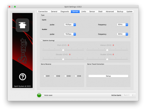
5.4 伺服器選項 (SERVOS TAB)
此選項用於伺服器配置,請注意確保伺服器正確的工作頻率,並設置使用的方向。
類型 (Type)
在這裡,根據您的伺服器製造商的規格設置中位,脈沖和頻率的值。
對於舊式舵機,頻率通常最大為60Hz。
輔助微調 (調校) (Subtrim (tuning))
在沒有安裝主旋頭的情況下,使用十字盤調平器對齊十字盤和伺服臂,使十字盤和伺服臂對主軸呈90度。
這通過勾選微調Subtrim (tuning)來完成。 當你勾選後, Spirit FBL將會把十字盤和伺服臂對主軸呈90度以方便調整球頭杆。注意的是在這時後,穩定(Stabilisation)將被禁用。
此時您可以輕鬆調整伺服器。 完成後,循環螺距與主軸完全垂直,此外,集體螺距應為0°(您也可以使用主槳來量度槳距角)。
在大多數情況下,伺服臂也必須對主軸呈90度。 所有舵機,CH1,CH2,CH3和CH4可分別設置在軟件各選項上。 CH1和CH3是副翼舵機。 CH2控制升降,CH4控制尾舵。
還需要設定尾舵的微調(Subtrim)和力學(即使用伺服臂力學最佳的那個孔,模型說明書有說明的),使伺服臂對其伺服器呈90度,尾舵螺距為0°。 此設置將影響尾舵的停止性能。
一旦設置,可以取消勾選 微調(Subtrim)關閉此特殊模式。
退出此特殊模式後,穩定模式和尾舵會再次工作。 請確保您的集體螺距通道在遙控器裡有正確的配置。 這意味著您應該在診斷(Diagnostic)中看到-100%到100%。 仔細檢查診斷(Diagnostic)中的0%是否與您的集體/油門遙控杆和集體螺距的中位相符(是線性的100% - 100%集體螺距曲線)。
伺服方向設置 (Servo reverse)
這允許您選擇哪個伺服器應該使用那個方向。 在改變集體螺距時後,所有舵機都應朝同一方向移動。 在這種設置之後,模型集體螺距應該對遙控杆的做出同一樣方向的反應。
這個參數是最重要的!
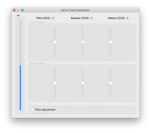
伺服器行程校正 (Servo travel correction)
在這裡,您可以單獨修改和更正每個伺服器的行程。 有些伺服器在行程的盡頭(Servo Limit)不太準確,這種不准確可能對飛行特性有負面影響。 在軟件的這一部分中,Spirit會切換到可進行這些更正的模式。
您應該使用十字盤調平器來確定在集體螺距的最低點和最高點沒有任何偏差。 對於正和負位置,需要個別在軟件裡設置 – 所以軟件裡有六個項目顯示。 如果行程少於遙控杆給的,您應增加該值。 如果太多的話,減少。 要選擇軟件裡那六個項目,你可以使用遙控杆進行。
如果直升機存在不對稱幾何導致如不能有相等的正負集體螺距值,您需要修改軟件裡所有三個伺服器的正或負滑塊。 如果您不確定,最好將滑塊留在中間。 (位置0)
5.5 伺服器盡頭設置項目 (LIMITS TAB)
此項目將影響伺服器盡頭(Servo limit)和行程(Servo Travel)的範圍。
十字盤環 (調整) (Cyclic Ring (tuning))
該參數設置電子十字盤環 (Electronic Cyclic Ring),允許模型實現最大的循環範圍,機械結構自由移動(例如伺服臂,推桿和連桿)。
該參數用作所謂的電子十字盤環。
首先,設定你想要的“集體螺距範圍”,例如+/- 12°。 我們推薦 在發射機中使用-100%至100%線性(Linear)的集體螺距曲線(Curve)。 現在請設置“副翼/升降”的最大的十字盤環(Cyclic Ring)的範圍。 嘗試設置最大的偏移。 該參數不會直接影響旋轉速度,但如果該參數太低,則該模型可能沒有一致的俯仰和滾動速率。 此設置應以0°集體螺距完成。 然後仔細檢查 最大遙控杆給的所有方向,以確保機械自由移動。 這也應該以最大和最小的集體螺距來完成。 一般情况下沒有理由設定角度高於最大集體螺距角度。
如果您增加了集體螺距的範圍,此參數必須再次檢查並進行調整,以確保機械是自由移動的。 如果選擇的十字盤環範圍不足,則可能在快速向前飛行(Fast forward flight)期間發生俯仰/機頭扯上(Pitch-up)(即使期間發生俯仰/機頭扯上(Pitch-up)補償達到最大值)。 這是因為模型無法添加足夠的校正與配置的範圍。
尾舵端點(調整)(Rudder end-points (tuning))
左/右端點 (L/R limit) - 設定主槳最小和最大偏轉。
我們建議跟據您的模型將兩面方向設置最大值。 否則尾舵
可能無法跟上高難度3D動作時的偏航(Yaw)方向。
請不要超過您的模型允許的限制。
5.6 傳感器選項 (SENSOR TAB)
此選項是設置裡最後一個重要部分。
靈敏度
撥盤可調節副翼,升降和尾舵軸的陀螺靈敏度。
“循環增益”(Cyclic gain) - 值越高控制迴路(Control loop)內的精度越高。 默認值為55%的增益,對於大多數模型,建議使用約60%。
“尾舵普通增益”(Rudder Common Gain) - 1.00x表示無倍數(一對一)。 這是550級直升機和較小模型的推薦值。 對於更大的直升機,可以調到 1.3x倍。 在您第一次飛行時,您的遙控器中的尾陀增益應配置為大約50%。
尾舵增益 (Rudder Gain) – 這參數撥盤只會在遙控器裡未分配尾陀螺儀增益通道時才會啟用。 它從遙控器裡取代尾舵陀螺儀增益(Gyro Gain)的功能,因此您可以直接在軟件中設置值。
軟件或遙控器中的尾舵可以通過以下方式進行設置:
- 鎖尾模式:1%至100% (Head-Lock mode)
- 正常(比例)或特殊功能模式:-100%至0% (Normal (Rate) mode)
負陀螺儀增益可用於激活救援或穩定模式 – 請檢查穩定(Stabi)選項。
有些遙控器的尾陀螺儀範圍為0至100%,其中50%為零增益(例如Spektrum DX6i)。 其他遙控器如是在-100%和100%的範圍,那0%是中間。
旋轉速度 (Rotation speed)
默認值為8,對初學者是剛剛好的,值越高,旋轉速度越快。 這個因素還取決於遙控器的機械聯動比率或D / R(Dual Rate),也取決於副翼/升降限制。
請確保該值不會太高,否則可能導致不必要或不精確的移動。
默認值 - 8
我們建議將循環旋轉速度(Cyclic rotation rate)設置在8 - 11範圍內。請記住,DFC轉子頭傾向於更快轉速,因此最好從默認值開始或以較低的值開始。
對於尾舵旋轉速度,飛行員喜歡在9 - 11的範圍。
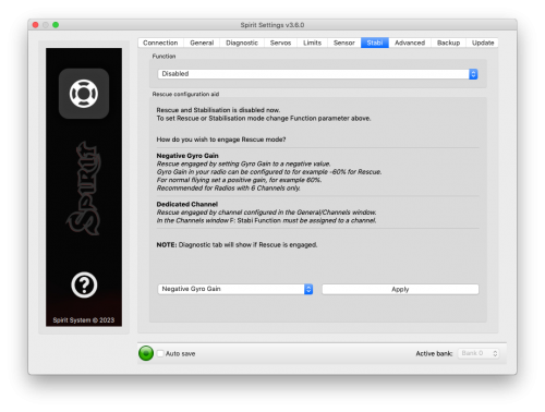
5.7 穩定選項 (STABI TAB)
Spirit FBL可提供模型穩定(Stabilization)或救援(Rescue)模式。穩定功能一旦被激活,系統將會將模型恢復到水平位置,而無需飛行員的任何輸入,這可以用作“紓緩”(Bail-out)功能 嘗試新的動作,並可以幫助學習過程。
救援模式幫助Spirit FBL的正常運作。 如果激活,模型將恢復到水平位置,並根據設置添加集體螺距。 當飛行員失去模型的方向感或控制時,該功能可以隨時使用。
Stabi模式頁面中有介紹如何設置救援或穩定模式。
從版本2.3.0起可以通過兩種不同的方法激活所選的“功能”:
- 負尾陀螺儀增益'
- 獨立的通道(新功能)
負尾陀螺增益適用於低通道數(6〜7)的遙控器。 當有未使用的通道時,這方法更好。
當前選擇的模式顯示在診斷(Diagnostic)選項中。
功能
這裡是您選擇在負尾陀螺儀增益下應激活哪種模式。
- 禁用 (Disabled) - 正常(比例)尾陀螺儀模式。(Normal (Rate) gyro mode.)
- 救援模式(正常)(Rescue (Normal)) - 將模型恢復到垂直水平位置 – 腳朝向地面方向。 這種恢復模式對於初學者來說非常有用。
- 救援模式(動態) (Rescue (Acro)) - 將模型恢復到水平位置,倒置或豎直,取決於激活時最接近的位置。 對於高階飛行員非常有用。
- 穩定模式(正常)(Stabilization (Normal)) - 穩定模式 - 腳朝向地面方向。 此模式有助於學習基礎飛行,如懸停或緩慢的轉換。 當你從遙控杆放手,模型會被推到水平位置。
- 穩定模式(動態)(Stabilization (Acro)) - 穩定模式 - 反轉倒飛或直立,取決於激活時最接近的位置。 這種模式適用於學習3D動作的基礎。 當你從遙控杆放手,模型會被推到水平位置。
- 穩定模式(比例模型)(Stabilization (Scale)) - 穩定模式 - 腳朝向地面方向。 此模式用於比例模型飛行。 陀螺儀模式為正常(比例)(Normal (Rate))而不是鎖尾。
- 同軸直升機模式 (Coaxial) - 穩定模式 - 反轉倒飛或直立,取決於激活時最接近的位置。 轉向行為與同軸直升機非常相似。 適用於學習停懸。
救援模式對BEC電流須求很大。請確保您的BEC可以處理電流高峰負荷。 如果您的BEC供電不夠模型可能會摔壞! 不要超過模型推薦的最高集體螺距,否則機械上可能在飛行過程中損壞!
副翼機械調整 (Flybar mechanic)
如果您的直升機配備傳統的副翼,您必須啟用此參數才能使用穩定或救援模式。 除了這個參數,所有的設置都是相同的。
救援模式的集體螺距 (Rescue collective pitch)
這參數設定在救援模式下模型拉高上升的速度。
100%表示在“伺服器”(Servos)選項中設置的集體螺距最大偏轉。
在第一次飛行之前(在沒有馬達/主漿上運行)檢查救援模式是否正常工作是非常重要的。
當直升機在地面上時,在救援模式下集體螺距或十字盤會推上或是正角度
遙控杆優先權 (Sticks priority)
這參數設定配置模式激活時的控制量。
值越高,模型越會跟據遙控杆給陀來反應。
方向控制率 (Direction control rate)
這設定穩定模式時的方向控制率。
低值非常適合初學者感覺上像開同軸直昇機的行為。 高的值更適合於比例模型飛行。
動態延遲 (Acro Delay)
這設定救援模式(正常)(Rescue (Normal))從倒飛回復到正飛之後激活的時間。 過了這個時間,救援的行為與救援模式(動態)的行為相同。 以這種方式,您可以更快地將模型拉高上升到安全的水平。
5.8 高階設置 (ADVANCED TAB)
此選項用於更高階的設置。 我們建議您在調整前完全了解這些參數。 調整這些值時你也必須設置模型的幾何。其他參數取決於飛行員的偏好。
幾何 6°(調整) (Geometry 6°(tuning))
為了Spirit FBL正確運作,您必須正確設置此參數。 這裡,Spirit將切換到特殊模式,在主槳上設置循環螺距為6°。 即副翼軸上的主槳角度為6°。 您需要用旋你的主槳令到模型的縱軸和主槳平行。 較高的值增加角度; 較低的減小。 最佳的幾何應在大約90 - 160範圍內。如果不在此範圍內,建議調整伺服臂的球頭距離或執行其他機械調整。
集體螺距方向 (Collective Direction)
這是集體螺距方向的參數。
在主漿是反方向轉(Trailing edge rotor head)的情況下(例如反時鐘方向轉),或如果主轉頭上有混合臂,請勾選“反轉選項”。 在大多數情況下,參數是不用打勾的。
升降軸過濾 (Elevator filter)
這個參數補償升降軸的彈跳。 值越大補償就越多。
如果該值太高,則可能導致升降軸柔軟的感覺。 我們建議使用默認值1來開始調。
循環前進 (Cyclic feed forward)
此參數用於設置您的遙控杆和模型之間的黏手感覺。 值越高越黏手和對於你給陀的反應更快。
如果該值非常高,會可能會發生升降軸反彈。
在tic-toc過程中,您還可以觀察到較高的馬達負載或副翼軸振盪,因為該模型不夠快地反應。
如果模型感覺不連貫並且不黏手,您可嘗試增加這值。
尾舵延遲 (Rudder delay)
這是平滑尾舵運動的參數。 它也有助於穩定尾舵 – 像是一種電子減速,類似於PID控制迴路裡的D。 伺服速度越快,“尾舵延遲”(Rudder delay)應越低。 對於舊式伺服器,我們建議將該值設置在20 - 25左右。對於較慢的電子數碼伺服器,設定在10 - 15之間。對於快速伺服(〜0.04s / 60°),值約為5.如果是無刷伺服器應建議設置值為0 - 2。
如果該值太高,尾舵可能會振盪,晃動或者會導致太滑的尾舵停止。
尾舵動態 (Rudder dynamic)
如果尾舵沒有正確停止,例如它有回彈,您可以使用此參數更改。
6 - 是默認值。
值越大,尾陀煞停得越強烈。 如果尾陀超過停止點而回彈,值則太高。 該參數也影響遙控杆給陀的響應速度; 更高的值意會有更更快的響應。 如果您無法在尾舵左右達到對稱停止,則需要確保尾部中心為0°。 或者,您可以降低尾舵左右盡頭的限制。
尾舵 - 混控 (Rudder -Revomix)
混控(尾部預測補償)會預先增加尾舵以對應集體螺距變化。 Spirit裡的混控和遙控器不同。 默認情況下,它會被關閉,用戶必須自行設置預測補償。
允許值為0到10,0是禁用; 在大多數情況下,不需要使用此參數,但是,使用較低的速度或性能較差的直升機時,可以使用該值設置。
自旋的一致性 (Pirouette consistency)
該參數決定了自旋的一致性和性能。 如果在某些操作中自旋不一致,請增加此參數值。
該值對於每個型號都是不同的,它取決於許多因素,例如:您的尾舵機構,主軸轉速等。在設置此參數之前,建議首先設置尾陀螺儀增益。
如果值太高,尾巴可能會快速或慢速搖擺。 它也可能導致停止性能差。 該值應在150到180之間。 對於無刷伺服器,建議將值提高10-15點。
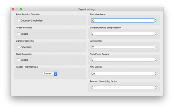
5.8.1 專家設置 (EXPERT SETTINGS)
對於微調,您可以設置以下參數。 通常不需要設置任何這些參數。
主軸旋轉方向 (Rotor Rotation Direction)
確定主軸旋轉方向的參數。 在大多數情況下,它是在順時鐘方向 - 參數是沒打勾的。
遙控杆死區 (Stick deadband)
確定遙控杆中心周圍的區域是系統識別不到任何移動。 如果通道讀數不精確,應增加值。 這可以在“診斷”(Diagnostic)選項中進行驗證。 此參數不能替代指數函數(Exponential function)。
升降軸俯仰補償 (Elevator pitchup compensation)
如果在快速向前飛行期間,模型對輸入的反應太快或者如果模型升降軸俯仰,增加該值直到不再發生。 如果直升機突然上升,這可能是由於太低和/或太多集體螺距,循環螺距範圍造成的。 在這種情況下,您必須將副翼/升降(Aileron/Elevator)的範圍增加到模型可以處理的高度。 如果這不能解決問題,您可以添加更多的補償。
循環相 (Cyclic phase)
該值是改變十字盤虛擬旋轉角度。
例如,90的值將使升降旋轉到副翼。 對於具有多主槳的型號(例如三個主槳頭),我們建議使用此功能。 對於大多數的其他型號,我們建議使用零值。
集體間距助力器 (Pitch Pump Booster)
為了實現類似有副翼集體螺距的行為,您可以增加此值直到達到理想的感覺。 請記住,更高的數值對於模型上的電源和伺服器的要求更高。
Signal processing
This parameter is used for operation on models with extreme vibrations that can't be eliminated in any way. This should be enabled only in cases when is absolutely necessary, because flight performance could be affected. It should increase precision of flight and also the precision of rescue and stabilization modes.
RPM Sensor Filter
In case that your RPM sensor has noisy output then RPM readout can be very unstable. This can lead to various problems with Governor. There may be a problem with spool up, flight mode switching or head speed jittering. To make RPM readout very precise, you may need to increase the value.
On the other hand, too high value can lead to a delay, that is unwanted for optimal Governor performance. So the value should be as low as possible while RPM readout is still precise. Variation of 1-20 RPM against the Requested RPM is optimal.
Autorotation Bailout rate
When performing autorotation the Bailout feature is available. The bailout is used to recover the headspeed faster than normally in order to achieve flying RPM. In this way pilot can regain full control of the model and continue in the flight. When using Spirit governor you can use this parameter to precisely set spoolup rate during the bailout. When Spirit governor is disabled, this settings has no affect.
5.8.2 TELEMETRY SETTINGS
ESC Telemetry is feature that enables transmission of the telemetry variables from the ESC to your radio. Covered in the ESC Telemetry page.
5.9 BACKUP TAB
Here, you can save the settings to your Spirit unit before powering off, you can also save the settings to your computer here, Should you need to reload them at a later date.
Profile
This section allows you to Save and Load complete settings of the unit to a specified file. If you have more than one of the same model, it is not necessary to carry out a complete setup again, just load the stored settings easily with the Load button.
Unit
Any changes to the configuration can be saved at any time to the internal flash memory of the unit.
To put all settings to a factory defaults, click Factory Settings.
Remember to save the settings each time you want to store the settings permanently. You must press the Save button. Otherwise, the changes will be lost after the Spirit FBL unit is turned off.
Bank Switching
In case that the Bank Switching is enabled, you can save the settings from single bank or even all banks. To see the differences between Banks you can use Bank Comparison feature.
5.10 UPDATE TAB
If you want to update the firmware, you can do so in this tab.
Firmware
First select the data file containing the firmware (*.4df) – Select button.Once the file is selected, press the Flash button. The upgrade progress will be displayed here. After completion, a confirmation dialog box should indicate a successful update.
Then, unplug the unit from its power source.
Upon the next start it will load with the newly flashed firmware.
Configuration of the unit is not changed, so you do not need to save/load it.
You can get firmware from: spirit-system.com.
6 BANK SWITCHING
This functionality allows you to switch between saved settings during a flight. Switching is done through the transmitter, so that channel's value is changed. This mean that a Bank can store one unique settings. The unit is able to store 3 different banks.
With a transmitter you are able to use a three position switch to switch freely between banks.
Bank switching is disabled by default, so you can decide whether it is useful in your application. You have to activate it by the assignment of Bank function in the General/Channels window. Generally, it is assigned to channel 7.
- Bank 0 – active in range of lower third (impulse under 1400μs).
- Bank 1 – active in range of mid third (impulse between 1400μs to 1640μs).
- Bank 2 – active in range of upper third (impulse above 1640μs).
Initial settings for Bank 1 and Bank 2 are equal to Bank 0. Bank 0 allow you to configure all parameters, while Bank 1, 2 does not allow to set main parameters. For safety, Bank 1 and 2 does not allow you to set any main parameters.
The Bank switching is great for switching between flight styles, sensor gains for low or high RPMs, for slow acro or 3D. Alternatively it can be used just for tuning your settings.
If the software is connected with the unit then bank switching by the transmitter is disabled. Then, Bank switching is performed using the software in bottom part of the window. When a bank is switched using the software it is necessary to save your settings to the unit before you switch Banks, or your settings will be returned to the previous (unchanged) state.
To verify that the Bank switching is working properly, please start the software and look at the Diagnostic tab. There you can see Bank indicator with the channel bar. Try to change position of assigned switch. If everything is correct, you will see that the Bank number will change there.
7 GOVERNOR
From firmware version 1.2 governor feature is available! You can use this feature instead of internal governor from your ESC or other governor. It is designed to work with electric, nitro and gasser helicopters. This can make flight performance even better because of constant head speed.
To achieve proper function it is very important to configure your ESC and then the unit. First from all make sure that internal governor is disabled in the ESC.
It is necessary to disassemble rotor blades from your model prior to the governor setup. Do not make any adjustments with motor turned on.
Governor feature can be used with the following receiver types:
Spektrum DSM2/DSMX, Futaba S-BUS, Jeti EX Bus, SRXL/SUMD.
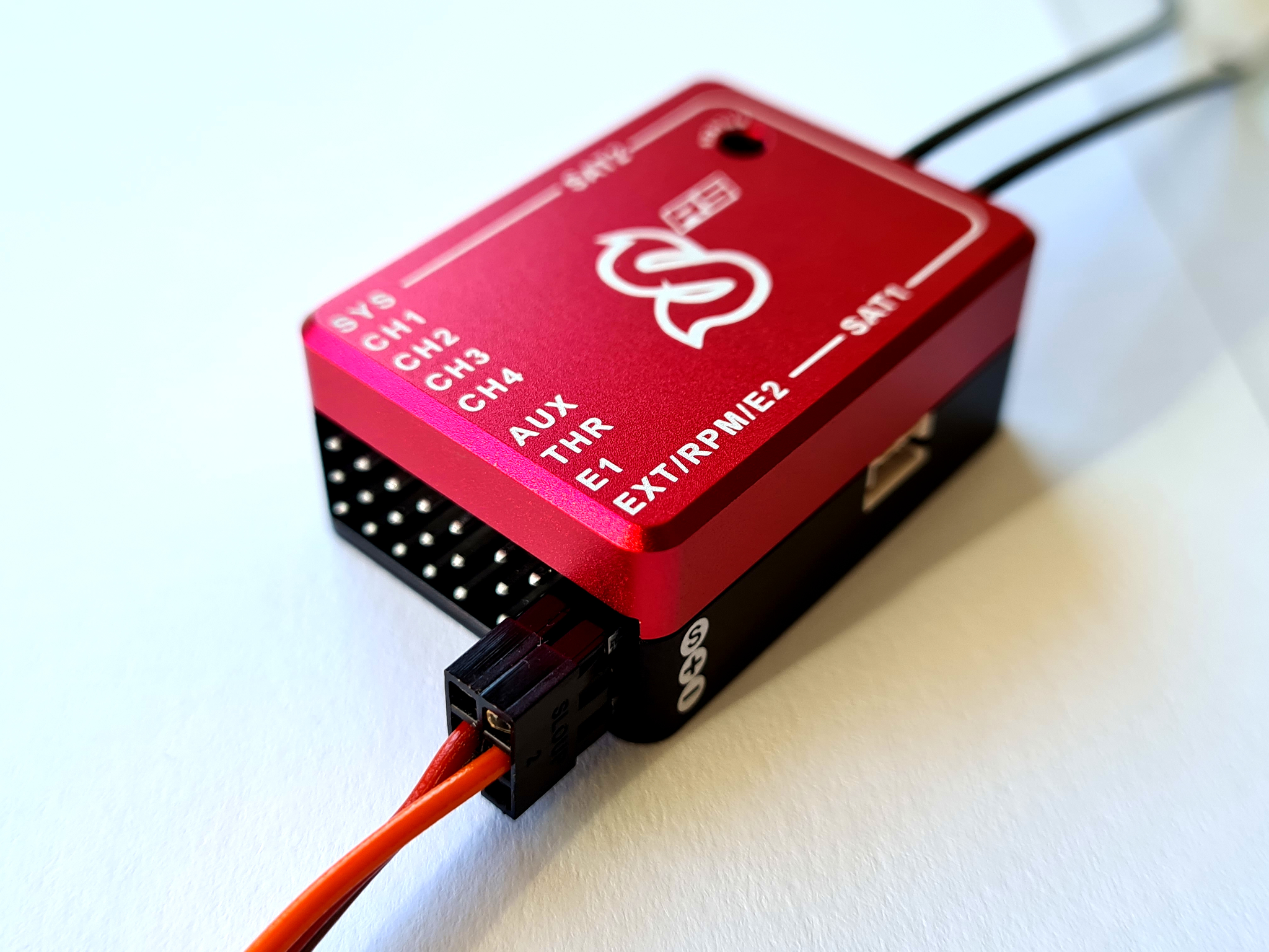
It is necessary to use throttle output from the unit when using governor. Throttle output is at the AUX port. You must connect the ESC or throttle servo there.
7.1 Sensor Wiring
Signal from a RPM sensor should be connected to the PIT pin (middle pin of the ELE/PIT/AIL port - Spirit and Spirit Pro).
- ESC with RPM output
- For electric helicopters the best and the easiest solution. You can use RPM output cable that is present on the ESC.
- ESC without RPM output
- In case that your ESC has no RPM output you will need a separate RPM sensor that can be connected to phases of the motor. Important is to power the sensor properly. Voltage can't exceed allowed level for the sensor. Recommended voltage range can be obtained from the sensor manufacturer. In case that the sensor require 3.3V you can connect it to the satellite connector in the unit (Details in the following photo). You can also use the Spektrum adapter.
- In case that the sensor is powered improperly it can be damaged along with the unit.
- Magnetic sensor
- For Combustion helicopters is necessary to use a sensor working on principle change magnetic field. In case that your ESC has no RPM output you will need a separate RPM sensor that can be connected to phases of the motor. Important is to power the sensor properly. Voltage can't exceed allowed level for the sensor. Recommended voltage range can be obtained from the sensor manufacturer. In case that the sensor require 3.3V you can connect it to the satellite connector in the unit (Details in the following photo). You can also use the Spektrum adapter.
- In case that the sensor is powered improperly it can be damaged along with the unit.
Red (+3.3V), Brown (GND).
7.2 Prerequisites
Electric
- Set throttle range in your transmitter so that 0% and 100% throttle position matches with value of the throttle bar in the diagnostics tab. This can be done by Subtrim function in your transmitter and/or Travel Adjustment function.
- Re-calibrate throttle range according to instructions of your ESC. In the most cases it can be configured by powering the model with throttle stick with 100% throttle and then by moving the stick down to 0%.
- If possible, configure fast spoolup mode in the ESC so the governor will be unaffected.
Nitro / Gasser
- Set the throttle range in your transmitter so that 0% and 100% throttle position matches with value of the throttle bar in the diagnostic tab. This can be done by Subtrim function in your transmitter and/or Travel Adjust function.
7.3 Activation
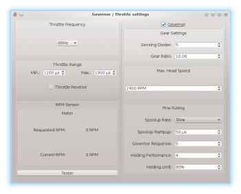
To activate Governor feature in the unit, you will need to assign Throttle function in the General tab/Channels. Then you will be able to enter Governor Settings in the General tab.
7.4 Settings
First from all basic settings are necessary so the governor can control the head speed correctly.
Throttle frequency
To achieve the fastest governor reaction it is necessary to set the highest possible frequency. For ESC it could be only 60Hz, but mostly all can work even with 200Hz. If you are unsure, please contact manufacturer of the ESC. For combustion helicopters it is max. operating frequency of the throttle servo.
Throttle Range
This parameter can affect output from the unit so you can fine-tune ranges precisely. For electric helicopters this parameter is optional. But in case that your ESC does not allow to calibrate throttle range correctly, you can do so here. For Nitro and Gasser helicopters you have to configure it always so the Throttle servo range matches range for the motor.
Throttle Range - Min.
Value of the lowest throttle signal. Default value: 1100 μs. For electric helicopters this value should be specified by manufacturer of the ESC. It is often specified in value of miliseconds (ms).
Parameter is optional - you do not have to change it if your ESC support the throttle calibration (e.g. by sticks).
You should set the lowest position when the motor is not spinning up anymore – is halted. While configuring this, the motor can start so you have to be very carefull.
Throttle Range – Max.
Value of the highest throttle signal. Default value: 1900 μs. For electric helicopters this value should be specified by manufacturer of the ESC. It is often specified in value of miliseconds (ms).
Parameter is optional - you do not have to change it if your ESC support the throttle calibration (e.g. by sticks).
The value should be configured to match with 100% throttle output programmed in your ESC or full throttle of the motor. If this parameter is not high enough you will be unable to tune Governor because there will be not enough room to compensate high loads. If configured too high then you can observe that after high load head speed will not drop immediately but can be there even for few seconds.
Throttle Reverse
Especially for Nitro and Gasser motors you can set correct compensation direction for the servo here.
Gear Settings - Sensing Divider
Electric motor: Motor poles / 2. For a 10 pole motor set divider to number 5. Mostly configured to 3 – 5.
Nitro/Gasser motor: Number of all active magnets. Mostly it is 1 – 2.
Gear Settings - Gear Ratio
Gear Ratio of the helicopter between the main wheel and pinion of the motor. For example: 120T main gear / 12T pinion = 10.
Max. Head Speed
Configure max. head speed that should be achieved with 100% throttle curve. For example: If you know that you won't exceed 2500 RPM then you can set the value to 2500. With 80% throttle curve your head speed will be 2000 RPM (2500 * 0.80 = 2000).
Fine-Tuning – Spoolup rate
Configure speed of the motor spoolup. For initial tests we recommend Slow spoolup rate.
Fine-Tuning – Spoolup Rampup
Value that will be added at the beginning of motor spoolup – when Hold is turned off. If the spoolup is not smooth, i.e. motor will start with a kick, the value is too high. If the spoolup has a delay, the value is too low. Default value of 50 μs should work fine in the most cases.
Fine-Tuning - Governor Response
This parameter is the most important one to achieve fast and proper response of the governor. It determine how fast the governor should react to a short-term load. Thus optimal settings are required. If configure too low or too high, rudder will not hold properly and can oscillate. Governor can greatly affect rudder performance so you can achieve better holding behavior. Too high value will result in overspeeding during e.g. pitch pump.
Fine-Tuning - Holding Performance
Determine how well the head speed is maintained during a long-term load. If value is too low then during e.g. tic-toc maneuver head speed can drop gradually. In case it is too high then after the tic-toc head speed can be higher than necessary and can even return to requested RPM with noticeable delay. It is better to start governor tuning process with low value.
7.5 Fine-Tuning Procedure
Firstly you have to finish basic setup including Max. Head Speed. Throttle curve in the transmitter must be FLAT. We recommend to set the throttle curve for example to flat 70%, 80% or 90%.
After disarming Throttle Hold you should immediately see Requested RPM in the software – this is desired head speed that should be maintained. Current RPM is head speed that is currently on the rotor head. If Current RPM is not calculated properly, then there is a problem with Gear Settings. In case that you can see zero or random Current RPM value then there is a problem with RPM Sensor and must be fixed.
Performance tuning procedure
We recommend to set the following values for the beginning:
- Governor Response: 5
- Holding Performance: 1
- You should start with increasing the Governor Response. You can do so until RPM is constant enough while doing aggressive collective pitch changes during hovering. When you will notice an overspeeding (RPM is higher than initially was) then the value is too high. In case that the value is too low or too high then the rudder performance can be affected negatively as well.
- When the Governor Response is well tuned, you can continue with increasing the Holding Performance parameter. In case that the value is too low, you will notice poor holding performance during demanding maneuvers with longer duration such as loop or tic-toc. If the value is too high, you can observe that the head speed is unstable even during stationary hovering.
Governor Response: 6 and Holding Performance: 5 may work fine for wide range of the helicopters.
- Throttle calibration of the ESC is possible only if the Governor is disabled in the unit.
- For throttle curve under approx. 50% governor is inactive – throttle is controlled directly.
- You should see “Governor was Engaged” event in the log after spoolup with enabled governor.
- Governor Bailout function can be activated whenever the throttle signal is higher than 1250 μs which is approx. 12% throttle curve. If the signal is lower then smooth spoolup sequence is activated.
- In case that the Current RPM value is 4000 RPM measurement is out of range. It may be needed to change count of the active magnets.
- If governor does not react correctly during Throttle Curve changes or even during spoolup, it is most probably result of an excess noise in the RPM sensor or connection. You may consider to use a proper shielding. Increasing value of the RPM Sensor filter in the Expert settings can solve the problem.
7.6 Sensor List and Troubleshooting
List of supported RPM sensors and their wiring is available on the Governor page.
You can also find there solutions for a various problems related with the Governor.
8 SOFTWARE KEYBOARD CONTROL
For fast and easy configuration we have implemented keyboard controls in the software.
| Shortcut | Function |
| F1 to F10 | Switch between tabs. |
| ESC | Exit current window. |
| CTRL + S | Save settings to the unit. |
| CTRL + P | Save profile to your computer. |
| CTRL + L | Load profile from your computer to the unit. |
| CTRL + W | Connection settings for the Wifi-Link module. |
| Numpad 0, 1, 2 | Switch between banks. |
| Tab | Switch between parameters. |
| Space | Select parameter / option |
| Arrows | Increase / Decrease value. |
| Page Up / Page Down | Increase / Decrease value by tens. |
| Home | Set the lowest value. |
| End | Set the highest value. |
