Difference between revisions of "Spirit RPM Sensor"
From Spirit System Manual
| Line 19: | Line 19: | ||
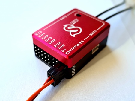
| − | <translate>Wiring Example</translate> | + | == <translate>Wiring Example</translate> == |
| − | [[File:SpiritSensor-connection.jpg|center| | + | [[File:SpiritSensor-connection.jpg|center|450px]] |
== <translate><!--T:15--> | == <translate><!--T:15--> | ||
Revision as of 11:41, 23 November 2021
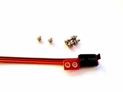
This sensor is HALL type which senses RPM by motion of the rotating magnets. Usually 1 - 2 neodymium magnets are mounted on the fan of combustion helicopters with a Nitro motor.
- Wire layout
- Orange wire: RPM Output Signal
- Red wire: Ground
- Brown wire: 3.3V - 15V
1 Wiring Example
2 Magnet mounting
We highly recommend to orientate each magnet as Active for a proper operation. More magnets will result in a higher reading resolution thus increased readout precision.
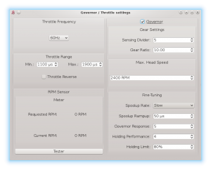
3 Governor Settings
When sensor is connected, please set the Sensor Divider parameter so that the value will represent count of the active magnets. Usually it is 1 or 2 magnets.


