Difference between revisions of "SpiritW1 Mounting"
(Created page with "<languages /> <div class=noprint><div id="up"></div></div> <translate> == Unit Mounting == <!--T:17--> <!--T:1--> Correct mounting of the Spirit W1 unit plays an important...") |
(No difference)
|
Revision as of 16:23, 22 December 2023
1 Unit Mounting
Correct mounting of the Spirit W1 unit plays an important role for the operation of your model.
Find a suitable location where vibrations are as low as possible - this is usually the same location shown by the manufacturer for mounting a gyro.
It is VERY important that the unit will be mounted so that the unit is exactly perpendicular to each rotational axis. Depending on your preference and available space it can be mounted in eight different positions:
- Horizontal (0°)
- Horizontal (180°)
- Horizontal (0° + inverted)
- Horizontal (180° + inverted)
- Vertical (0° - left side)
- Vertical (180° - left side)
- Vertical (0° - right side)
- Vertical (180° - right side)
In case the unit is positioned so that connectors are facing forwards, select 180°, please. If the unit is mounted upside down, select inverted option.
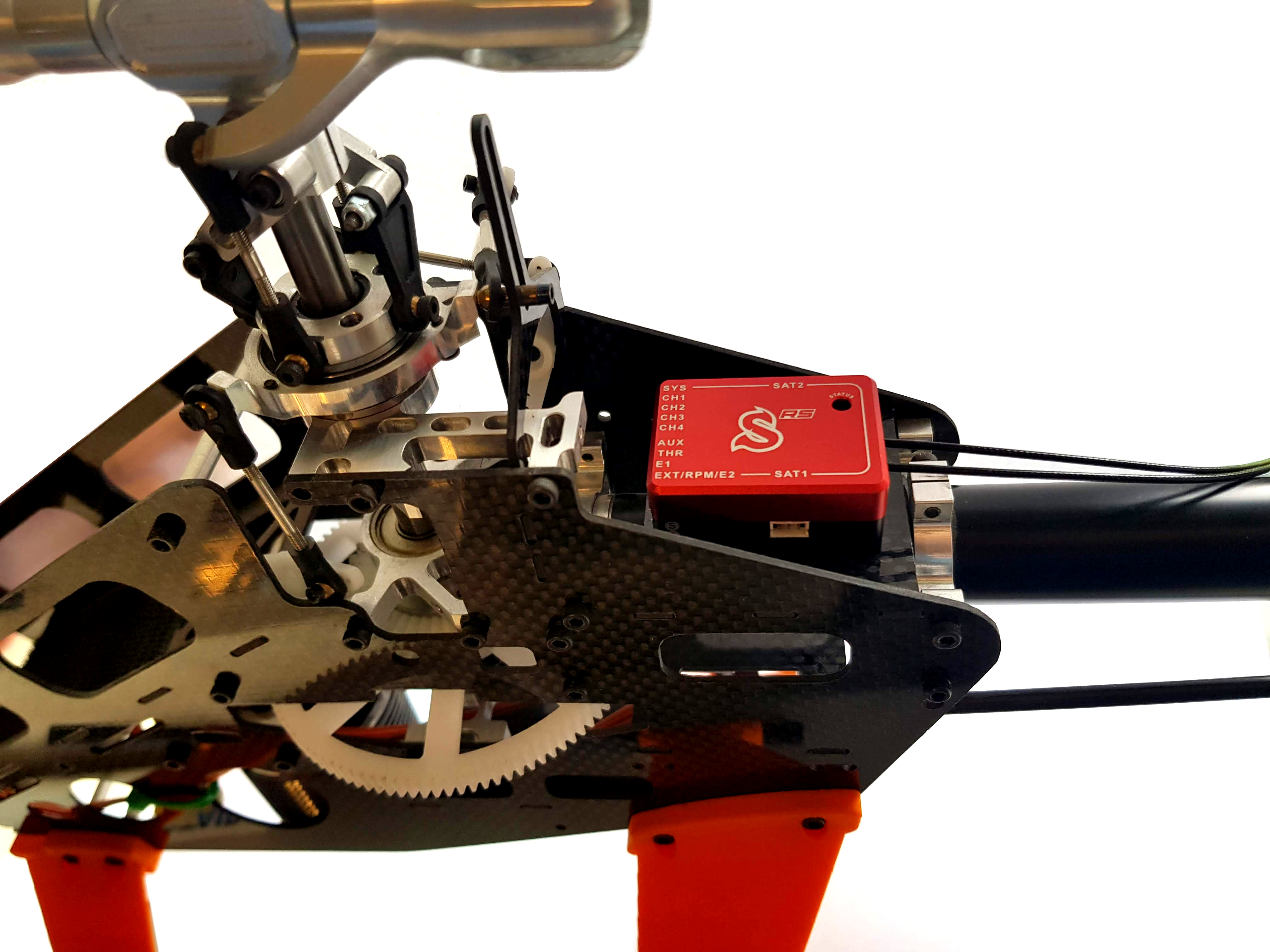
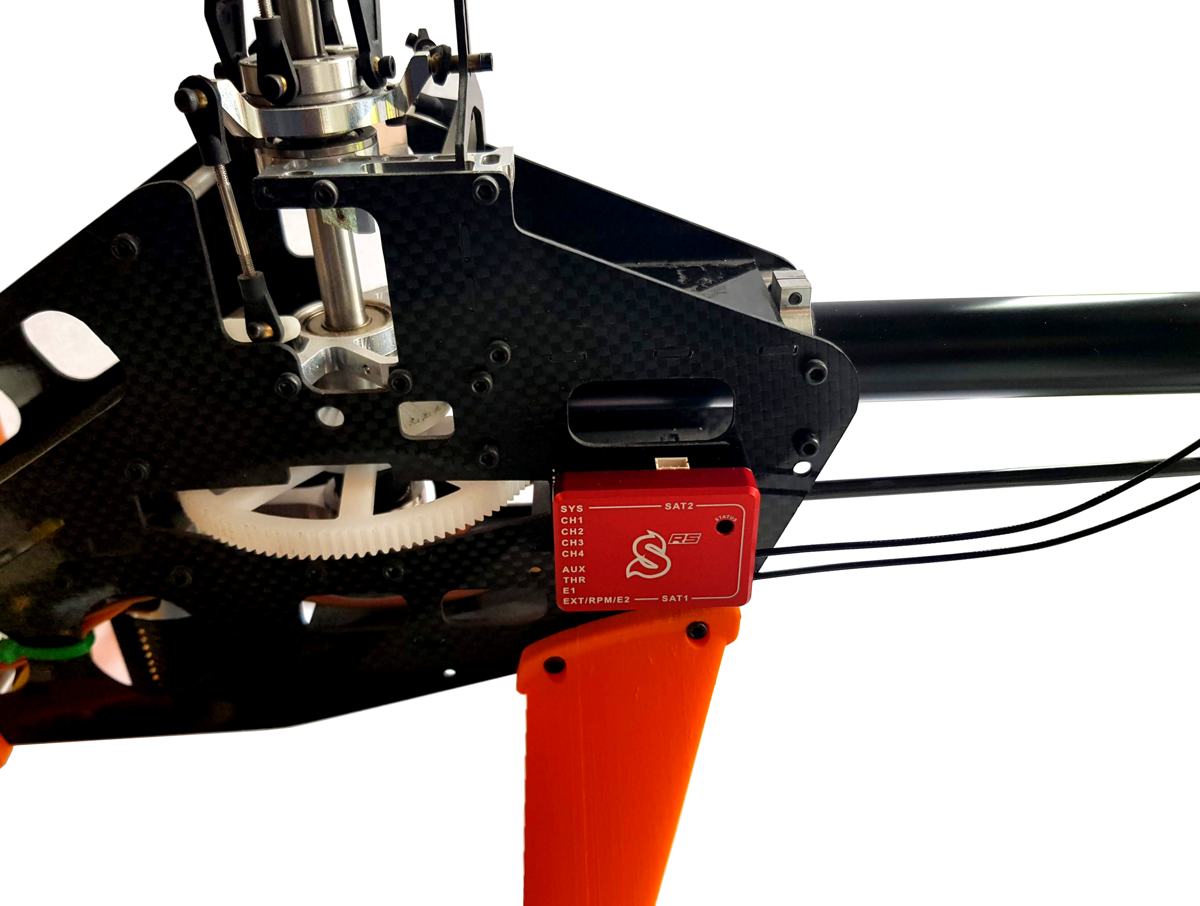
In the following photo the unit is mounted by double-sided adhesive tape to the frame of model.
In order to better insulate against any vibrations from the model, it is necessary
to choose the right double-sided mounting tape. The tape should limit any
transmission of vibrations from the model to the Spirit which may produce
undesirable flight characteristics.
Vibrations may also be caused by incorrectly balanced blades, damaged
bearings, bent shafts and other mechanical issues.
We recommend to use supplied double sided tape.
2 Antenna
Spirit W1 is equipped with 2 full-range antennas. For the best signal reception it is necessary to mount them properly at the model.
Ideally ends of the antennas should be perpendicular to each other in all directions.
Do not bend antennas more than 45° in a sharp angle. Bending radius should be more than 2 cm.
Do not cover antennas with any additional objects. Preferably direct visibility at any angle should be achieved.

