Cablaggio
Spirit può essere utilizzato come giroscopio di coda autonomo o come sistema senza flybar o come unità di stabilizzazione flybar.
Contents
- 1 GYRO E FLYBAR
- 2 FLYBARLESS
- 3 ORIENTAMENTO DEL CONNETTORE
- 4 CABLAGGIO DEI SERVO
- 5 ESC/MOTOR WIRING
- 6 CONNECTION OF STANDARD RECEIVER (PWM)
- 7 CONNECTION OF SPEKTRUM DSM2/X SATELLITE
- 8 CONNECTION OF FUTABA S-BUS RECEIVER
- 9 CONNECTION OF PPM RECEIVER
- 10 CONNECTION OF JETI EX BUS RECEIVER
- 11 CONNECTION OF SRXL/SUMD RECEIVER
1 GYRO E FLYBAR
I proprietari di elicotteri con flybar possono sfruttare il giroscopio di mantenimento della rotta, che mantiene la coda nella direzione data dal trasmettitore indipendentemente dagli effetti del vento o da eventuali forze esterne.
Collegare il servo del timone alla porta "CH4" dell'unità Spirit. Se si utilizza anche un ricevitore standard, sarà necessario collegare GEAR (o AUX) dal ricevitore alla porta AUX sull'unità Spirit. Inoltre, sarà necessario collegare la porta RUD del ricevitore alla porta RUD dell'unità Spirit.
Anche se hai un modello con flybar, puoi anche collegare l'unità nello stesso modo in cui faresti con uno flybarless. Ciò consente di utilizzare tutto il potenziale dell'unità, comprese le modalità di stabilizzazione e salvataggio. Affinché questo funzioni correttamente, è necessario abilitare il parametro "Flybar Mechanic" nella finestra Advanced / Expert durante il setup. Tutti gli altri parametri possono essere configurati esattamente come con una testa senza flybar.
2 FLYBARLESS
Gli elicotteri senza flybar possono sfruttare tutte le capacità dell'unità Spirit. Lo Spirit stabilizzerà il modello su tutti gli assi e lo renderà anche meno influenzato dal vento, allungherà i tempi di volo e aumenterà l'agilità del tuo modello. Se impostate correttamente, le caratteristiche di volo dovrebbero essere più stabili, il che ti darà la sicurezza di eseguire anche le manovre più impegnative.
Le pale del rotore senza flybar sono anche diverse dalle pale progettate per i modelli con flybar. Per caratteristiche di volo ottimali si consiglia di utilizzarli. Quando si utilizza l'unità Spirit come sistema senza flybar, tutti i servi devono essere collegati nelle posizioni corrispondenti:
3 ORIENTAMENTO DEL CONNETTORE
Prima di collegare qualsiasi connettore all'unità Spirit, controllare attentamente le istruzioni seguenti. Guarda come collegare tutti i cavi nel giusto orientamento rispetto all'unità Spirit che hai.
3.1 μSpirit
La disposizione dei pin dei connettori 'JST-ZH (R) è diversa' dai connettori Servo standard. Il filo MARRONE (centrale) è il pin GND. Il filo ARANCIONE è il pin SIGNAL. Il filo ROSSO è + 5V (tensione BEC). Utilizzando i cavi 'JST-Servo' è possibile collegare un Servo classico e tutte le periferiche Spirit al μSpirit anche con connettori Servo.
3.2 Spirit e Spirit Pro
Tutti i cavi collegati all'unità devono essere orientati in modo che il filo del segnale (filo ARANCIONE) sia più vicino all'etichetta del pin del connettore, verso il centro dell'unità. Questo orienta il negativo (filo MARRONE) verso il bordo dell'unità.
3.3 Spirit 2
Tutti i cavi collegati all'unità devono essere orientati in modo che il filo del segnale (filo ARANCIONE) si trovi nella parte superiore dell'unità. Questo orienta il negativo (filo MARRONE) nella parte inferiore dell'unità.
4 CABLAGGIO DEI SERVO
Le unità spirit hanno pieno supporto per tutti i tipi di servocomandi. Si prega di procedere secondo l'installazione guidata nel software Spirit Settings per vedere come collegare correttamente i servi.
Spirit è pre-programmato per un impulso servo neutro di 1520 µs e una frequenza di 50Hz - assicurati di aver selezionato i parametri servo corretti come specificato dal produttore del tuo servo.
Se l'impulso neutro del tuo servo / i è diverso da quello sopra, come 760µs, non collegare ancora questo servo perché potrebbe essere danneggiato.
Alcuni connettori hanno dimensioni non standard che potrebbero interferire con i connettori vicini dopo aver collegato l'unità. Come soluzione, consigliamo di sostituire questi connettori con tipo JR o Futaba.
Non collegare mai un connettore per l'alimentazione dell'unità nelle posizioni SYS o ELE / PIT / AIL o si rischia di danneggiare l'unità.
| μSpirit |
| CH1 – Pitch / Alettoni servo |
| CH2 – Servo dell'elevatore |
| CH3 – Servo Alettone / Pitch |
| CH4 – Servo timone di coda / ESC timone |
| Spirit, Spirit 2 |
| CH1 – Pitch / Alettoni servo |
| CH2 – Elevator servo |
| CH3 – Aileron / Pitch servo |
| CH4 – Rudder servo |
| Spirit Pro |
| CH1 – Pitch / Aileron servo |
| CH2 – Elevator servo |
| CH3 – Aileron / Pitch servo |
| CH4 – Rudder servo |
| CH0 – auxiliary (optional) cyclic servo for CCPM 90 swashplate type. |
Servos at positions CH1 and CH3 are dependent on the Swashplate settings. Aileron servo on the model is mostly positioned on the right side while pitch on the left side.
5 ESC/MOTOR WIRING
Electronic Speed Controllers (ESCs) for electric motors or Throttle Servos for combustion motors can be connected in two ways:
- In the receiver - Throttle port (Failsafe is handled by receiver)
- In the Spirit unit - AUX (AUX1) port (Failsafe is handled by unit and/or additionally by receiver)
Wiring details for each receiver type are described always in the particular scheme - see next sections.
With Spektrum DSM2/X satellites throttle must be connected always to the unit.
By default Throttle output from the unit is disabled for all receiver types (except Spektrum DSM2/X). Assign Channel 1 in the General/Channels - Throttle.
In order to use Governor it is always required to use Throttle output from the unit.
Throttle frequency that can be configured in the unit can stay at default settings (60Hz). Only if Governor is used it is usefull to set as high frequency as possible. Recommended values are described in the Governor page.
5.1 Castle ESC
If Castle ESC is used, please configure following Throttle parameters in the General - Throttle/Governor window:
- Throttle Frequency: 60Hz.
- Throttle Range - Min.: 1060 us.
- Throttle Range - Max.: 1940 us.
All other ESCs should work well with default settings. If not, please use the Factory default.
5.2 Throttle Servo
For combustion helicopters it is required to set optimal travel range in order to prevent a binding. If the servo is connected in the unit, you can set absolute limits that can never be exceeded. These can be configured in the General - Throttle/Governor - Throttle Range.
It is also possible that Throttle Reverse will be necessary to get fully closed condition when Throttle Hold is engaged. This will change servo movement direction.
5.3 µSpirit and Rudder ESC/Motor
µSpirit unit has full support for motor driven tail rotors. These motors are usually driven by a dedicated ESC. To control the motor standard servo signal is used. Connect Rudder ESC at the CH4 port. In the Setup Wizard it is necessary to set Rudder - Control type to Motor.
Lastly make sure you will set Throttle range for this ESC. Please see description of the Rudder End-points in the Configuration/Limits tab section.
In order to turn off the Tail motor when Main motor is not running it is necessary to later assign the Throttle channel. See the Channels assignment in the Configuration/General - Channels section. This can be changed anytime after the basic configuration.
6 CONNECTION OF STANDARD RECEIVER (PWM)
μSpirit – receiver type: PWM
Spirit – receiver type: PWM
Spirit Pro – receiver type: PWM
Spirit 2– receiver type: PWM
For standard receivers it is necessary to use two normal and one special cable. Three connectors from the special cable should be plugged into the receiver and the end of these cables to the unit.
The unit is powered by two cables from the receiver. These are connected to the AUX and RUD positions. The Throttle (ESC or Throttle servo) should be connected to the receiver.
The easiest way you can start is to connect a cable between the RUD port with Rudder output of the receiver. Then continue with the AUX port which should be connected to the Gyro Gain channel output of the receiver. Next, connect the Aileron, Elevator and Pitch channels. If you are not sure whether you have the correct output or not, you can plug in one servo and power the unit to verify that your connection is correct. This can be repeated for each servo. The Diagnostic tab in the software is very helpful too, because you can see whether the connection is correct even without connected servos.
For Spektrum receivers you can view the Spektrum PWM connection scheme.
Spirit Pro, Spirit 2
The unit is able to control Bank Switching by 7th channel of the receiver. Connect the cable to the AUX2 port and allow Bank Switching in the software.
Never plug a connector for powering the unit to SYS or ELE/PIT/AIL ports.
7 CONNECTION OF SPEKTRUM DSM2/X SATELLITE
μSpirit – receiver type: Spektrum DSM2/X
Spirit – receiver type: Spektrum DSM2/X
Spirit Pro – receiver type: Spektrum DSM2/X
Spirit 2 – receiver type: Spektrum DSM2/X
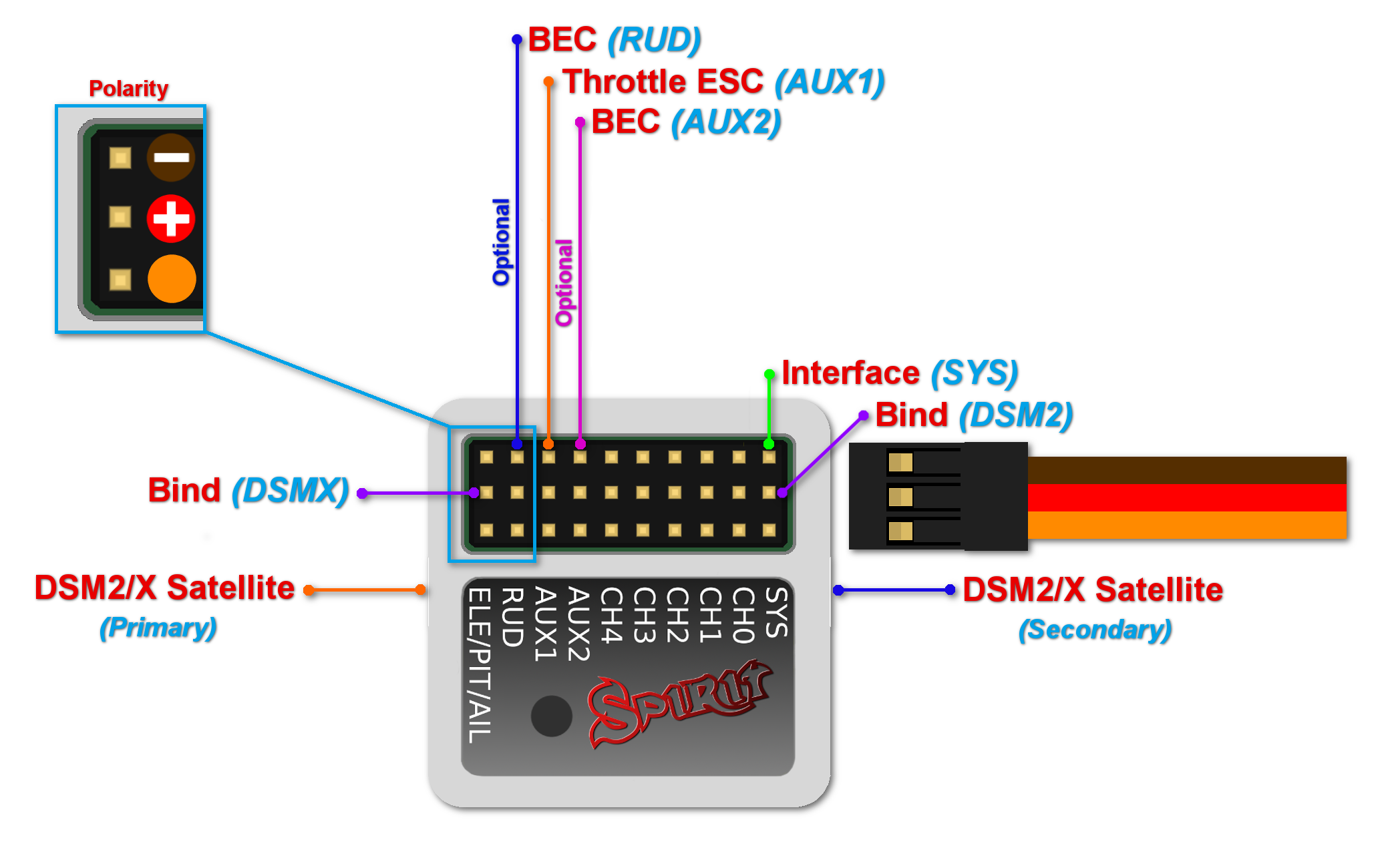
Connection to a BEC is optional. If the model is powered by an external BEC, this must be connected to the RUD port. Also the power lead from the ESCs internal BEC must be disconnected.
Spirit
A second satellite can be connected, but this can only be achieved via a special adapter connected to the RUD port. This adapter can be purchased separately. Before satellites can be used they must be bound to your transmitter, taking into account any failsafes that need to be set. To use both, two satellites and an external BEC, be sure to use a Y-harness made from large gauge wire to supply the high current that is needed.
Spirit Pro, Spirit 2
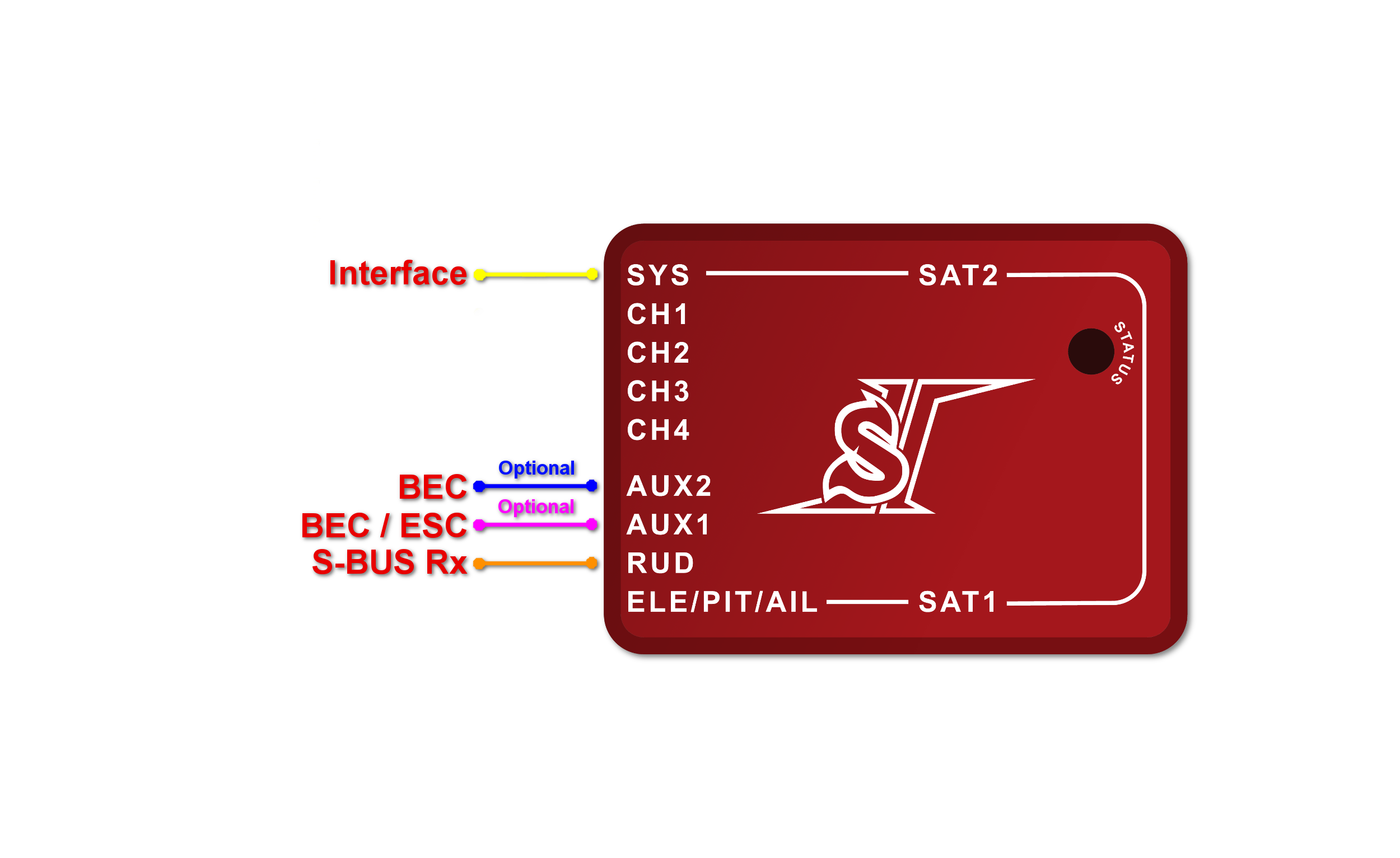
You can connect two satellites directly to the unit. If you want to use only one satellite, you have to use the Primary (SAT-1) connector.
To bind the satellites, insert a bind plug in the SYS port for DSM2 satellites or the ELE/PIT/AIL port for DSMX satellites. Power cycling the Spirit start the bind process. Once successfully bound, the STATUS LED will go out and the satellite LED will come on.
If the second satellite fails to bind, swap the satellites and repeat the bind process.
Be sure Receiver type in the software is configured to Spektrum DSM2/X otherwise binding process will not work. Never plug a connector for powering the unit to SYS or ELE/PIT/AIL positions.
7.1 Spektrum Multi Adapter
Spektrum Multi Adapter allows to connect additional 2 Spektrum DSM2/X satellites.
It is suitable for all Spirit units and is recommended when using GeoLink module and/or ESC telemetry that is using a satellite ports. Before usage please bind satellites that are intended to be connected at the adapter through primary and secondary ports.
Servo cable: RUD port
Orange wire: AIL pin
Spirit
With this adapter it is possible to connect up to 3x Spektrum satellites at the same time.
Spirit Pro, Spirit 2
With this adapter it is possible to connect up to 4x Spektrum satellites at the same time.
8 CONNECTION OF FUTABA S-BUS RECEIVER
μSpirit – receiver type: Futaba S-BUS
Spirit – receiver type: Futaba S-BUS
Spirit Pro – receiver type: Futaba S-BUS
Spirit 2 – receiver type: Futaba S-BUS
Spirit
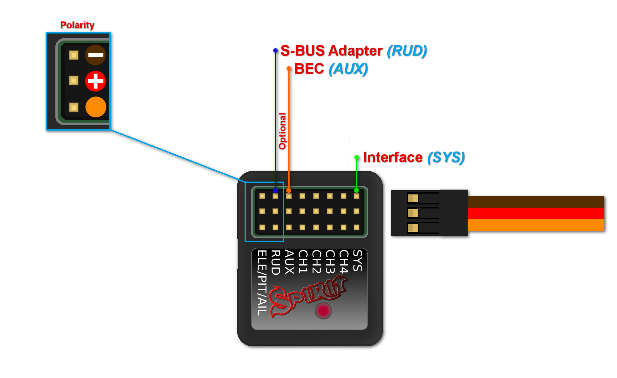
When using S-BUS it is necessary to use an inverter that replaces the cable between the receiver and the Spirit unit's RUD port. The inverter cable - called SBUS Adapter - can be purchased separately. The SBUS Adapter has to be connected in the way, that longer end is directed to the unit and shorter to the receiver. This apply for both Futaba and FrSky receivers.
μSpirit, Spirit Pro, Spirit 2
Connect the receiver with the unit by normal patch cable to the RUD port. You can use cable that is included in the package.
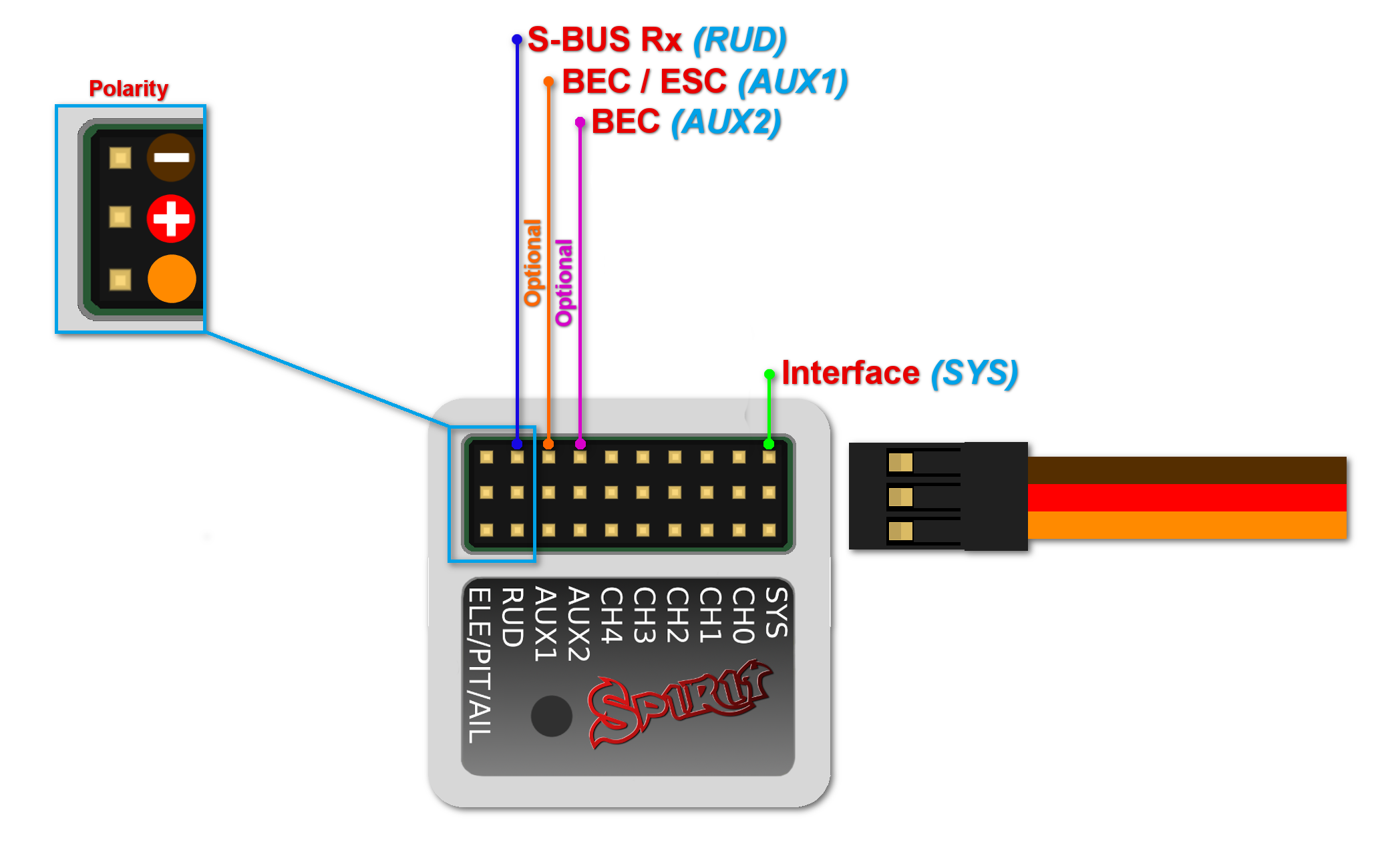
Connection to a BEC is optional. For models of 500 size and larger it is recommended to use dual power supply cables due to the increased power consumption. That means besides the S-BUS cable, an additional power supply cable should be connected to the AUX port.
When using this type of receiver you can connect the throttle cable directly to the receiver. Alternatively, you can assign the throttle channel in the software and use the AUX as throttle output from the unit.
Never plug a connector for powering the unit to SYS or ELE/PIT/AIL ports.
9 CONNECTION OF PPM RECEIVER
μSpirit – receiver type: PPM
Spirit – receiver type: PPM
Spirit Pro – receiver type: PPM
Spirit 2 – receiver type: PPM
Connection to a BEC is optional. For models of 500 size and larger it is recommended to use dual power supply cables due to the increased power consumption. That means besides the communication cable, an additional power supply cable should be connected to the AUX port.
When using this type of receiver you can connect the throttle cable directly to the receiver. Alternatively, you can assign the throttle channel in the software and use the AUX as throttle output from the unit.
Never plug a connector for powering the unit to SYS or ELE/PIT/AIL ports.
Futaba pilots with PPM receiver such as R6107SP will need to reconfigure channels according Futaba PPM page.
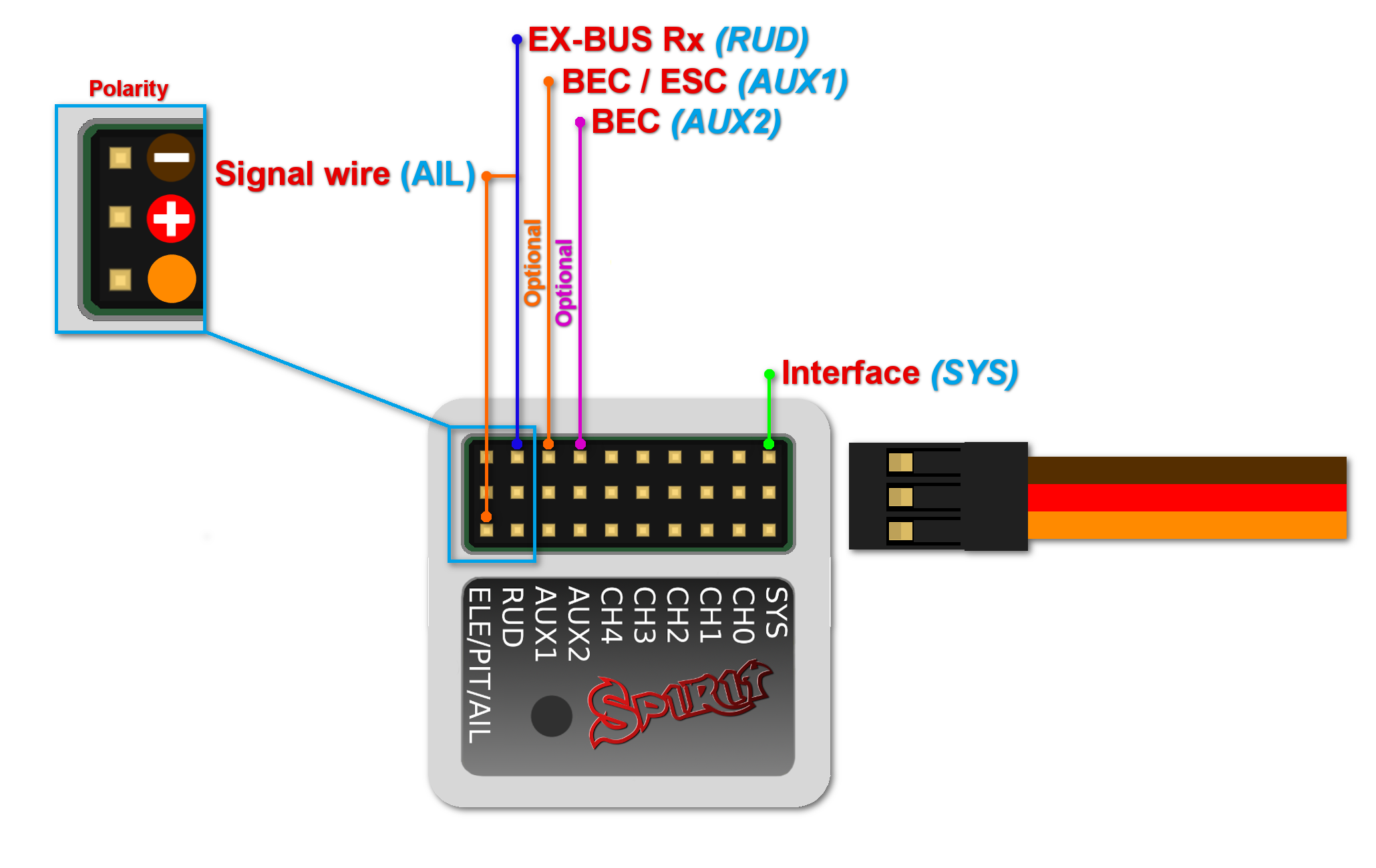
10 CONNECTION OF JETI EX BUS RECEIVER
μSpirit – receiver type: Jeti EX Bus
Spirit – receiver type: Jeti EX Bus
Spirit Pro – receiver type: Jeti EX Bus
Spirit 2 – receiver type: Jeti EX Bus
This connection type now supports the new integration with JETI Model transmitters. You can now fully configure the Spirit unit remotely through the JETI Model transmitter.
Remember to configure the receiver type through the software or the integration will not work. Also, it is necessary to download Spirit.bin file from the website. Move the file to the Devices directory in the SD card of your transmitter.
For futher instructions please check the Jeti Integration page.
Connection to a BEC is optional. For models of 500 size and larger it is recommended to use dual power supply cables due to the increased power consumption. That means besides the EX Bus cable, an additional power supply cable should be connected to the AUX port.
When using this type of receiver you can connect the throttle cable directly to the receiver. Alternatively, you can assign the throttle channel in the software and use the AUX as throttle output from the unit.
A special cable is needed to enable this communication. Signal wire (Orange) is connected to the AIL pin, while power wires (Red and Brown) are connected to the RUD port in the unit. For JETI REX receivers, end of the special cable is connected to the EX1 or EX2 (depending on the receiver configuration). For EX receivers, please use EXT port.
Never plug a connector for powering the unit to SYS or ELE/PIT/AIL ports.
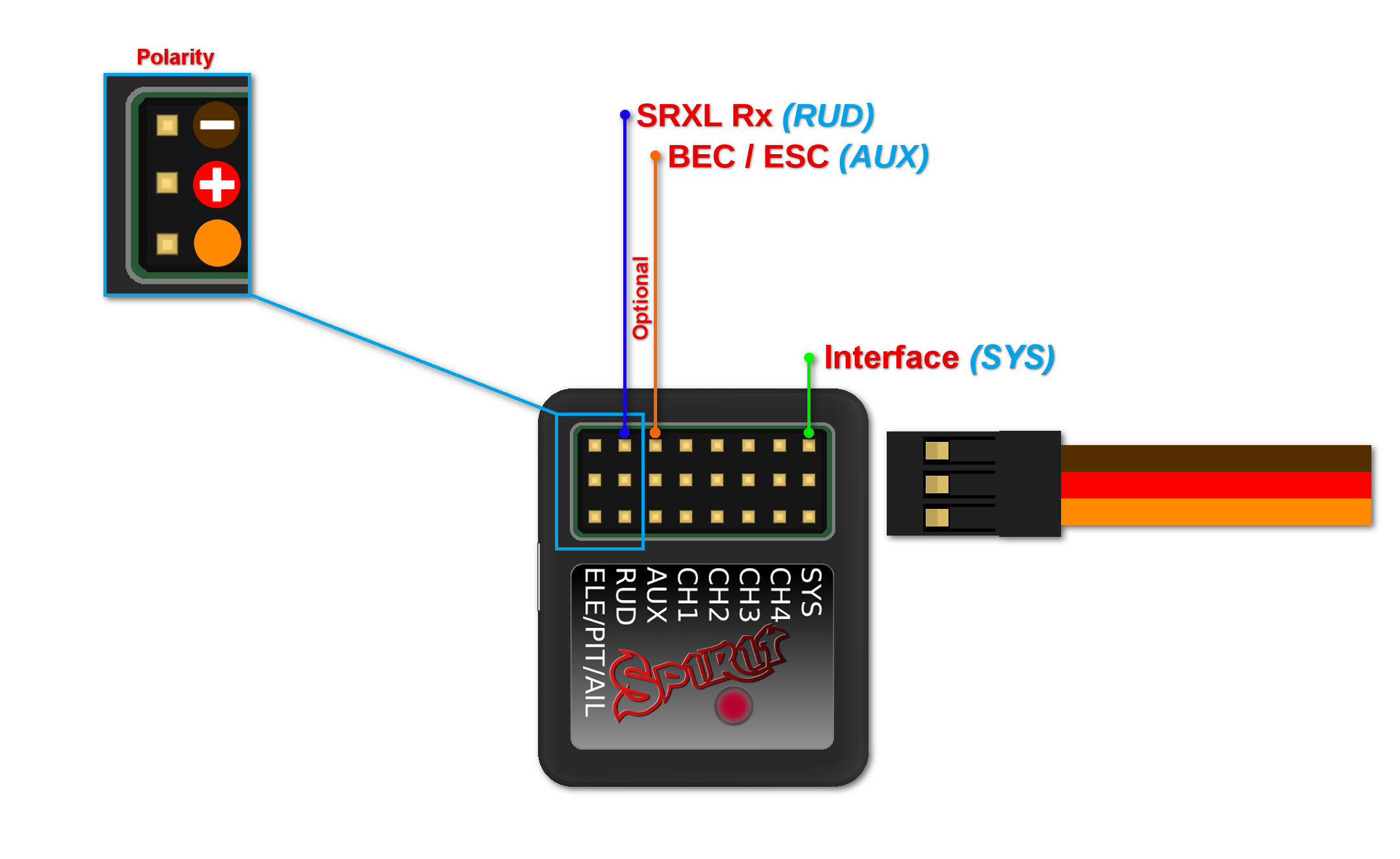
11 CONNECTION OF SRXL/SUMD RECEIVER
μSpirit – receiver type: SRXL/SUMD
Spirit – receiver type: SRXL/SUMD
Spirit Pro – receiver type: SRXL/SUMD
Spirit 2 – receiver type: SRXL/SUMD
Connection to a BEC is optional. For models of 500 size and larger it is recommended to use dual power supply cables due to the increased power consumption. That means besides the communication cable, an additional power supply cable should be connected to the AUX port. This protocol family can work with a wide range of receivers. Thus you can use Multiplex SRXL, BeastX SRXL, Graupner SUMD, Jeti UDI, Spektrum SRXL, JR X-Bus (mode B) and more.
When using this type of receiver you can connect the throttle cable directly to the receiver. Alternatively, you can assign the throttle channel in the software and use the AUX as throttle output from the unit.
Never plug a connector for powering the unit to SYS or ELE/PIT/AIL ports.


