GeoLink Konfiguration
Contents
1 GeoLink Support
GeoLink funktioniert erst ab der Firmware 2.5. Um alle Funktionen nutzen zu können, müssen sie zunächst die Unterstützung in der Spirit Einheit aktivieren. Gehen sie dazu auf den Reiter Settings - General tab first und hacken sie Geolink an. Danach speichern sie die Einstellungen in der Spirit Einheit und starten das Spirit neu.
2 Kompass Kalibrierung
Alle GeoLink Module wurden vollständig getestet und kalibriert. Das einzige was der Pilot möglicherweise benötigt, ist eine Neukalibrierung des integrierten Kompasses. Der Kompass ist entscheidend für die Funktionen des GeoLink und eine korrekte Navigation. Der Kompass erfasst das Erdmagnetfeld und kann somit den Kurs bestimmen. Leider ist das Erdmagnetfeld überall anders. Der integrierte Kompass wurde in der Tschechischen Republik kalibriert und getestet. Wird das Modell außerhalb der Tschechischen Republik betrieben ist eine Neukalibrierung des Kompasses von Nöten. Generell empfiehlt es sich den Kompass direkt auf dem Flugfeld zu kalibrieren.
2.1 Überprüfung der Kalibrierung
Um zu prüfen ob das GeoLink richtig kalibriert ist, starten sie die "Spirit Software" und öffnen das "GeoLink Fenster". Auf der Registrierkarte Information können sie den aktuellen Werte sehen. Ganz unten wird die Ausrichtung in Grad angegeben.
Platzieren sie nun das GeoLink so nahe wie möglich in Richtung Norden, sodass die Flugrichtung des Modells dem Pfeil entspricht. Vergleichen sie dies idealer weise mit einem analogen Kompass.
Wenn das Modell Richtung Norden ausgerichtet ist, soll der Wert 90°+- 4 sein. Dieser Wert soll nicht weit davon entfernt sein. Weicht der Wert ab, muss eine Neukalibrierung erfolgen.
Wir empfehlen kein Smartphone sondern einen analogen Kompass zur Kontrolle zu verwenden, da die digitalen nicht kalibriert sind und diese sich auch nicht kalibrieren lassen. Ein analoger Kompass ist die BESTE Methode zur Kontrolle
2.2 ungewöhnliches Verhalten
Ist der Kompass falsch kalibriert, werden sie feststellen das Funktionen wie Geo-Fence, Return to Home und Position Hold nicht richtig funktionieren. Wenn zb Return to Home aktiviert ist und das Modell die Position erreicht hat und sich das Modell kreisförmig um die Position herum bewegen, anstatt stabil zu stehen. Je größer diese Kreisform ist desto grösser ist der Kalibrierungsfehler. Wenn dieses Verhalten auftritt, ist es ein deutliches Zeichen für eine Rekalibrierung.
2.3 Kalibrierungsprozess
Um die Kalibrierung durchzuführen verbinden sie die Spirit Einheit mit der Software. Klicken sie im Reiter Allgemein auf GeoLink/Einstellungen und dann auf den Reiter Modul. Klicken sie auf Neu Kalibrieren. Jetzt können sie das Spirit ausschalten und das USB Kabel entfernen.
- Beim erneuten Einschalten des Spirit werden sie feststellen, dass die LED am GeoLink 3 mal schnell blinkt. Das zeigt an das GeoLink Modul im Kalibrierungsmodus ist.
- Die LED zeigt ihnen dann den Fortschritt der Kalibrierung an. Bewegen sie das Modell in alle Richtungen und Winkel um eine Kugel zu imitieren. Jedes LED-Blinken zeigt an das neue Daten erfasst wurden.
- Das Modell nun so lange drehen und wenden bis die LED periodisch blinkt. Ab diesen Punkt ist die Kalibrierung abgeschlossen und nach einem Neustart ist das GeoLink einsatzbereit.
Für 600er+ Helikopter empfehlen wir die Kalibrierung nur am GeoLink durchzuführen da die Größe des Helikopters unhandlich ist.
Die Kalibrierung empfiehlt sich idealerweise direkt am Flugfeld zumachen um bessere Werte und genügend Platz zuhaben jedoch ist es im Innenbereich ebenso möglich.
Die Software erkennt das Geolink nicht während der Kalibrierung. Wurde der Kalibrierungprozess einmal angestoßen lässt sich dieser nicht mehr deaktivieren. Der Prozess muss abgeschlossen werden dass das GeoLink wieder betriebsbereit ist. Wird das GeoLink während dem Prozess von der Stromversorgung getrennt, beginnt dieser wieder von vorne beim nächsten Einschalten.
3 Konfiguration
Als erstes muss sich der Pilot entscheiden welche GeoLink Funktionen er nutzen möchte. Information über die einzelnen Funktionen entnehmen sie auf der Seite Funktionen. Der Pilot kann bei Bedarf mehrere Funktionen gleichzeitig aktivieren.
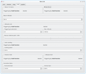
Überprüfen sie die Funktion die sie verwenden möchten in dem GeoLink Fenster unter dem Reiter „Einstellungen“. Nach dem Aktivieren (Häkchen) sind die verfügbaren Parameter für die jeweilige Funktion verfügbar. Durch ändern der Parameter kann das Verhalten der ausgewählten Funktion angepasst werden um die Anforderungen zu erfüllen. Für die ersten Versuche empfehlen wir mit den Standartwerten zu beginnen
3.1 Triggering
You can verify if triggering mechanism is working correctly even before actual flight by checking the Aid tab. If a feature is engaged you will see ACTIVE or in other case Inactive.
For safety reasons do not engage any GeoLink feature before model is in the air at appropriate altitude.
3.1.1 Stabi function
By default all GeoLink features are engaged as soon as a Stabi function is active. For example if Coaxial or Rescue mode is engaged the GeoLink feature is engaged as well and complement operation of a Stabi function by acting simultaneously. We recommend to set Stabi/Function to Coaxial mode for Geo-fence, Return to Home and Position Hold features.
3.1.2 Dedicated GeoLink channel
Alternatively you can assign a GeoLink feature to any free channel in the General/Channels window. In the right part of the Spirit Settings software select which feature you would like to assign. (for example F: Return to Home). Then select appropriate channel which will be used for engaging. You can use same channel for multiple features at the same time.
4 Geo-fence
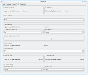
To enable this feature it is required to tick the CheckBox in the GeoLink window/Aid tab.
4.1 Usage
The feature can be engaged at any given time by a command from your radio. It is important to decide in which way the feature can be engaged as there are two options.
- To engage with Stabi function - in this case the feature is engaged when programmed Stabi function is engaged. This mean you do not need to assign any other switch than when used for e.g. Stabilisation mode
- To engage with assigned GeoLink channel - it is required to assign F: GeoLink Geo-fence function in the General/Channels to an available channel.
Please make sure that Geo-fence Area was defined. Four points must be programmed. The Spirit Settings will display right order to program all points.
4.2 Modes
If Geo-fence is engaged by assigned GeoLink channel there is possibility to use tri-state switch also for programming of a new Geo-fence area. In the Channels window you will be able to see Function as On (1), Off and On (2) which is corresponding to 100%, 0% and -100% channel value.
When On (1) is displayed it mean that at this point Geo-fence is engaged and flight area is restricted. The model will return upon exceeding the area to the center of the area. Then pilot have to touch the aileron or elevator stick in order to continue in flight.
When On (2) is displayed the unit is in a programming mode which allow to overwrite current Geo-fence to the new with position at which the model currently is. Please note that it will not work if model is flying or if GNSS signal is very weak.
4.3 New Geo-fence programming
It is possible to program the Geo-fence either with the Spirit Settings by selecting 4 points at the Map. Or there is possibility to use GeoLink channel to do so even if you are out of a computer.
If assigned GeoLink channel is used you have to set On (2) function state and keep it on for at least 2 seconds. At this period Status LED of the Spirit unit will turn off and after 2 seconds new Geo-fence point is programmed. Pilot has to define four points that will determine new area. To program all four points pilot have to engage the programming four times. Only once all points are programmed the Status LED of the Spirit unit will turn On which will signalize success. New area is applied immediately.
5 Altitude Limit
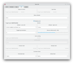
To enable this feature it is required to tick the CheckBox in the GeoLink window/Aid tab.
5.1 Usage
The feature can be engaged at any given time by a command from your radio. It is important to decide in which way the feature can be engaged as there are two options.
- To engage with Stabi function - in this case the feature is engaged when programmed Stabi function is engaged. This mean you do not need to assign any other switch than when used for e.g. Stabilisation mode
- To engage with assigned GeoLink channel - it is required to assign F: GeoLink Altitude Limit function in the General/Channels to an available channel.
5.1.1 Triggering Acceleration
This parameter is key for engaging the Rescue mode fast enough if your model is approaching towards the ground. The faster is descending velocity, the faster the Rescue is engaged. This mean that the Rescue can be engaged above configured Minimum limit to save the model safely. If model is approaching the Minimum limit slowly then the rescue is engaged at configured level. Low Triggering Acceleration value is causing only minor difference.
6 Return to Home
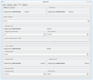
To enable this feature it is required to tick the CheckBox in the GeoLink window/Aid tab.
6.1 Usage
The feature can be engaged at any given time by a command from your radio. It is important to decide in which way the feature can be engaged as there are two options.
- To engage with Stabi function - in this case the feature is engaged when programmed Stabi function is engaged. This mean you do not need to assign any other switch than when used for e.g. Stabilisation mode
- To engage with assigned GeoLink channel - it is required to assign F: GeoLink Return to Home function in the General/Channels to an available channel.
6.2 Modes
If Return to Home is engaged by assigned GeoLink channel there is possibility to use tri-state switch also for programming of a new Home spot. In the Channels window you will be able to see Function as On and Off states. When Off is visible the feature is not used in any sense. When On is visible you can enter several modes of the feature.
6.2.1 On (1)
Channel value 57% - 100% : When On (1) is displayed it mean that at this point Return to Home is engaged and model will move to the Home spot. This is what you might want to engage during flight.
6.2.2 On (2)
Channel value -100% - -62% : When On (2) is displayed the unit is in a programming mode which allow to overwrite current Home spot to the new with position at which the model currently is. Change will affect all Banks - if used. Please note that it will not work if model is flying or if GNSS signal is very weak.
6.2.3 On (3)
Channel value -61% - -38% : When On (3) is displayed the unit is in a programming mode which allow to overwrite current Home spot to the new with position at which the model currently is. Change will affect only active Bank - if Bank Switching is used. Please note that it will not work if model is flying or if GNSS signal is very weak.
6.2.4 On (4)
Channel value 27% - 56% : When On (4) is displayed it mean that at this point Return to Home is engaged and model will move to the Take-Off position. Take-Off position is programmed automatically during each Take-Off. This mode can be used stright with no Home position programming.
6.3 New Home position
It is possible to program the Home position either with the Spirit Settings by selecting a point at the Map. Or there is possibility to use GeoLink channel to do so even if you are out of a computer.
If assigned GeoLink channel is used you have to set On (2) function state and keep it on for at least 2 seconds. At this period Status LED of the Spirit unit will turn off and after 2 seconds new Home position is programmed. Once finished the LED must turn On again.
7 Auto Landing
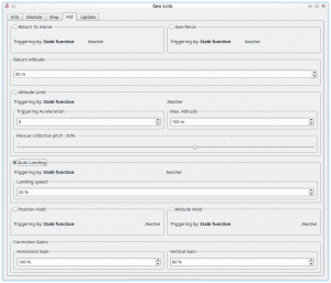
To enable this feature it is required to tick the CheckBox in the GeoLink window/Aid tab.
In order to make the landing as safe as possible set the Landing Speed value. We recommend to start with a low values and increase it to a speed that is suitable for the model. With too high value the landing might be too hard. Default value of 25̤̤% should work well for the most models.
7.1 Usage
The feature can be engaged at any given time by a command from your radio. It is important to decide in which way the feature can be engaged as there are two options.
- To engage with Stabi function - in this case the feature is engaged when programmed Stabi function is engaged. This mean you do not need to assign any other switch than when used for e.g. Stabilisation mode
- To engage with assigned GeoLink channel - it is required to assign F: GeoLink Auto Landing function in the General/Channels to an available channel.
8 Position Hold
To enable this feature it is required to tick the CheckBox in the GeoLink window/Aid tab.
8.1 Usage
The feature can be engaged at any given time by a command from your radio. It is important to decide in which way the feature can be engaged as there are two options.
- To engage with Stabi function - in this case the feature is engaged when programmed Stabi function is engaged. This mean you do not need to assign any other switch than when used for e.g. Stabilisation mode
- To engage with assigned GeoLink channel - it is required to assign F: GeoLink Position Hold function in the General/Channels to an available channel.
9 Altitude Hold
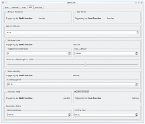
To enable this feature it is required to tick the CheckBox in the GeoLink window/Aid tab.
9.1 Usage
The feature can be engaged at any given time by a command from your radio. It is important to decide in which way the feature can be engaged as there are two options.
- To engage with Stabi function - in this case the feature is engaged when programmed Stabi function is engaged. This mean you do not need to assign any other switch than when used for e.g. Stabilisation mode
- To engage with assigned GeoLink channel - it is required to assign F: GeoLink Altitude Hold function in the General/Channels to an available channel.
9.2 Modes
If Altitude Hold is engaged by assigned GeoLink channel there is possibility to use tri-state switch also for disabling Collective Pitch input. In the Channels window you will be able to see Function as On (1), Off and On (2) which is corresponding to 100%, 0% and -100% channel value.
When On (1) is displayed it mean that altitude in which the feature was engaged will be held. Pilot is still able to change Collective Pitch, but in a limited manner. Collective Pitch reaction will be slower than in a normal flight mode.
When On (2) is displayed it mean that altitude in which the feature was engaged will be held. Pilot is unable to change Collective Pitch by pitch stick. So that Collective Pitch steering is fixed and is changed only by GeoLink in order to hold right altitude.
10 Correction Gains
GeoLink features are doing a certain movements to achieve desired position of the model. These movements are small corrections which are dependent on parameters of the model. For very agile models these correction can be smaller. While for heavy and big models you might need bigger in order to reduce time required to achieve desired position.
10.1 Horiontal Gain
Horizontal gain affects features such as Geo-fence, Return To Home and Position Hold. For example if Return to Home feature is engaged and it takes too long to return at programmed home spot it is necessary to increase Horizontal correction. Too high value will result in excess (too visible) corrections even when model is maintaining spot on position.
10.2 Vertical Gain
Vertical gain affects features such as Altitude Limit and Altitude Hold. When model is oscillating in altitude it is necessary to decrease value until it will stop. It is recommended to adjust and check the behavior in no wind. Too high value will result in a more apparent oscillations. Starting with default gains is advised.

