Difference between revisions of "Configuration/es"
(Created page with "Algunos transmisores tienen un rango de 0 a giróscopo 100% donde el 50% es el medio - ganancia de cero (por ejemplo, Spektrum DX6i). Otros usan un rango de -100% y 100%, dond...") |
(Created page with "Funkce") |
||
| Line 453: | Line 453: | ||
</div> | </div> | ||
| − | ''' | + | '''Funkce'''<br />Here is where you select which mode should be activated at negative gyro gains. |
<u>Disabled</u> - Normal (Rate) gyro mode. | <u>Disabled</u> - Normal (Rate) gyro mode. | ||
Revision as of 13:16, 19 September 2016
La configuración es la siguiente y uno de los pasos más importantes para el correcto funcionamiento del sistema.La configuración se realiza mediante el software, que combina la eficiencia y simplicidad al tiempo que ofrece parámetros ajustables, incluyendo parámetros avanzados.
El software ofrece el Asistente de configuración. Se recomienda utilizar el asistente, ya que le guiará a través de la configuración de todo desde el principio hasta el primer vuelo.
Contents
1 CONEXION AL PC
Antes de comenzar la configuración real es necesario para conectar el sistema a un ordenador mediante un puerto USB. Dependiendo del sistema operativo y el ordenador, puede necesitar ser instalado después de conectar el cable al puerto USB de un conductor.
La configuración Spirit está disponible para los siguientes sistemas operativos:
- Microsoft Windows
- Apple OS X
- GNU/Linux
- FreeBSD
Una vez conectado y el controlador se ha instalado con éxito un nuevo puerto COM virtual debe ser visible en el software y el dispositivo de gerente.
MICROSOFT WINDOWS
Instale el controlador a través de la instalación de software. Este proceso se describirá en una sección siguiente.
APPLE MAC OS X
Para funcionamiento correcto es importante descargar e instalar el controlador desde la siguiente URL:
http://spirit-system.com/dl/driver/SiLabsUSBDriverDisk.dmg
GNU/LINUX a FreeBSD
Es necesario instalar nada.
1.1 WIFI-LINK
The Spirit Settings software can be connected with Wifi module from now. It is called Spirit Wifi-Link. Wifi-Link can completely replace the USB interface. Thus user can perform all the settings wirelessly. You can find description of the connection with all instructions in the Wifi-Link guide.
2 CONEXION CON LA UNIDAD
Si ya ha conectado la interfaz USB al ordenador, al lado conecte el cable de interfaz al puerto SYS de la unidad de Spirit FBL. La unidad Spirit FBL no puede ser alimentado desde el puerto del cable / SYS USB por lo que es necesario alimentarlo desde ya sea el receptor, un BEC o una batería externa. Los puertos RUD y AUX se utilizan para alimentar la unidad Spirit FBL y si el uso de un BEC o paquete de baterías se sugiere para conectar a estos puertos con un voltaje entre 3V y 15V. El hilo medio debe ser la conexión de tensión positiva.
Nunca conecte un conector para la alimentación de la unidad a SYS o ELE/PIT/ELE puertos.
NOTA
Si la unidad no esta configurada (por ejemplo, una nueva unidad) se recomienda no conectar cualquier servos todavía.
3 CONFIGURACION INSTALACION DE SOFTWARE
El software de configuración está disponible en la página web del Sistema Spirit: spirit-system.com/.
MICROSOFT WINDOWS
Ejecute el instalador y siga el asistente. Si el controlador no está instalado todavía, se le dará la opción de hacerlo durante el proceso de instalación.
El instalador pasa por todos los pasos necesarios para preparar el equipo para ejecutar el software de configuración. Una vez finalizado el proceso de
instalación, el software de configuración se puede iniciar desde el escritorio o en la lista de programas, „Spirit Settings“.
APPLE MAC OS X
Instale el software descargado abriendo el archivo DMG y luego mover el contenido a la carpeta Aplicaciones. Software de configuración se puede iniciar desde la carpeta Aplicaciones con „Spirit-Settings“.
GNU/LINUX a FreeBSD
Extraer todos los archivos desde el archivo descargado para, por ejemplo, el directorio de inicio.Software de configuración se puede iniciar desde el directorio recién creado con el archivo „settings.sh“.
4 CONFIGURACION SOFTWARE
Una vez instalado el software, asegúrese de que su unidad de Spirit está conectado a través de USB al puerto SYS, encendido e inicializado (luces LED están encendidos), a continuación, ejecutar el software en su ordenador.
Start the Spirit Settings from your desktop or a directory where it was installed.
NOTA
El software de configuración debe iniciarse después de que la unidad ha inicializado. Cada vez que el Spirit FBL es inicializado (LED de estado está encendido) y
conectado, puede realizar ajustes en la configuración.
Configuración durante el vuelo no es posible debido a los riesgos de seguridad asociados.
PROBLEMAS CON WINDOWS
Si el software de configuración no puede detectar un puerto COM válido, puede intentar iniciar el software como administrador. Como alternativa, marque el número de puerto COM. Si el valor es demasiado alto intente configurar el número de puerto (dispositivo Silabs)
para, por ejemplo, COM1 - COM4. Para portátiles también vale la pena deshabilitando funciones de ahorro de energía USB en el Administrador de dispositivos.
5 USO DE SOFTWARE
Después de la conexión exitosa de la unidad Espíritu FBL, todas las características de configuración deben ser accesibles. Si no, trate de elegir otro puerto COM (dispositivo) o tratar de reiniciar el software, desconecte el aparato de la fuente de alimentación y repetir el procedimiento.
Asegúrese de que el software se puso en marcha después de que la unidad a inicializado.
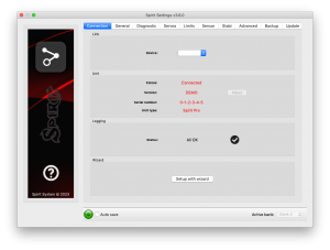
5.1 CONNECTION TAB (FICHA CONEXION)
Esta tabla indica el estado actual de la conexión, le informa acerca de la versión actual del firmware, muestra el número de serie de la unidad conectada y le permite cambiar el puerto COM. Además cuenta con un asistente para la configuración inicial.
Recomienda utilizar este asistente, ya que le guiará a través de una configuración básica de la manera más fácil y sencilla.
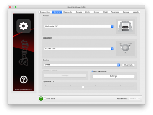
5.2 GENERAL
Si ya ha configurado la unidad mediante el asistente, puede realizar ajustes adicionales a su configuración aquí. Todos los valores se refieren a la configuración seleccionada en el asistente.
NOTA
Cada vez que se cambian los parámetros, el nuevo valor se aplica inmediatamente pero no se guarda. A menos que la configuración se guarda de forma manual, después de desconectar la fuente de alimentación todos los cambios no guardados se perderán. (ver ficha Copia de seguridad.)
Posicion
Selecciona la posición en la que la unidad está unido al modelo.
(Vea la sección 3 - Instalación)
Swashplate
Seleccione el tipo de ciclico de su modelo.
En la mayoría de los casos es CCPM 120° o 120° CCPM (invertida).
Cualquier mezcla de resaca en el transmisor debe estar apagado. Se debe establecer en H1 (servo único) tipo.
Receiver
Seleccione el tipo de receptor que está utilizando:
PWM – receptor standar.
PPM – conexion de linea unica.
Spektrum DSM2/DSMX – DSM2 o DSMX satelite.
Futaba S-BUS – receptor conectado via SBUS.
Jeti EX Bus – receptor conectado via EX Bus (for JETI model integration).
SRXL/SUMD – receptor conectado via SRXL, SUMD, UDI.
Flight style (estilo de vuelo)
Establece cómo el modelo se comportará en vuelo. Este parámetro se utiliza para controlar y adaptar el comportamiento de vuelo de acuerdo con los requisitos del piloto.
Los valores más bajos significan que el modelo se comportará de una manera más consistente, controlado y se sentirá más robótico. Los valores más altos significan un comportamiento más natural. La respuesta a los movimientos de palo será más flybar similares.
Este parámetro no afecta a la forma estable será el modelo. La mayoría de los pilotos prefieren valor predeterminado de 4.
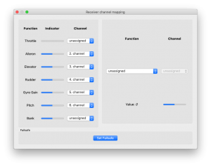
Channels (Canales)
Después de hacer clic en el botón, se mostrará la ventana con asignación de canal.Puede asignar cualquier canal a cualquier función aquí. El número de canales disponibles depende del tipo de receptor. Recuerde sólo asignar un canal a cada función.
Cuando se asigna un canal para la función del Acelerador (Throttle), el acelerador de salida de la unidad se puede obtener de la posición AUX.
Cuando se asigna un canal para la función del Banco, a continuación, se activa la conmutación del Banco (véase el capítulo 5.6).
Cuando se asigna un canal para la función de Gyro Gain, es posible configurar la ganancia del giróscopo directamente a través de este programa en la pestaña del sensor. El canal no asignado podría ser utilizado de otra manera, por ejemplo, para la conmutación del Banco.
Failsafe (a prueba de fallos)
Para un PPM, Spektrum DSM2/X, Jeti EX Bus, tipos de receptores SRXL/SMUD puede establecer la prueba de fallos directamente en la unidad. Valores de canal se almacenan inmediatamente después de hacer clic en el botón Establecer a prueba de fallos. En caso de que la señal se pierde por más de 1 segundo se estableceran los valores de forma automática en el vuelo.
Con otros tipos de receptores de prueba de fallos se ha programado en el transmisor o receptor.
Realtime tuning
By assignment of a parameter (P) it is possible to change the settings directly from your transmitter.
You can comfortable set selected parameter by changing channel value (for example by a potentiometer).
Thus you do not need a configuration software at all. Usual transmitter is enough.
A change in corresponding channel will immediately change value of the parameter. Maximal deflection will set the highest value of the parameter, while the minimal deflection will set the lowest value.
Realtime parameter tuning has the highest priority. So when enabled, saved value from the profile or a Bank will be ignored.
This functionality is enabled only when the configuration software is not connected. This will prevent from a possible collisions. As soon as the software is disconnected, selected parameter is configured by the channel value. In case that the software is started again, it will keep value from realtime tuning in it's memory. However, with opened software policy described above will be applied again (Realtime tuning is inactive and value will be intact even if channel is changed).
You can configure 3 different parameters and functions simultaneously with this feature.
If function (F) is assigned, it is engaged when it's value is equal to 1. Vibration analysis function allows you to measure vibrations during the flight. It is described later in the Diagnostic tab section.
When parameter tuning is complete, it is recommended to open the software and save the settings to the unit. Then unassign the parameter so the value can't be changed anymore.
NOTE
It is recommended to always carry extreme caution to not lose control of the model!
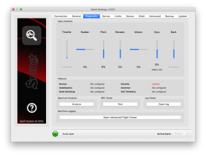
5.3 DIAGNOSTIC TAB (FICHA DIAGNOSTICO)
Una vez que los ajustes de la ficha anterior se han terminado, ahora se recomienda hacer los ajustes y cambios necesarios en el transmisor para que los controles de la emisora coinciden con las salidas de los sistemas de visualización. Generalmente, cada transmisor es diferente y el centro del canal no es exactamente el mismo. El desgaste y las influencias ambientales también pueden tener un efecto haciendo que el centro de los canales a fluctuar. Otra consideración es el valor máximo y mínimo de cada canal. Aquí, a ajustar su tiros usando los ajustes de punto final servo transmisor.
NOTA
Para un correcto funcionamiento de la unidad, es necesario que el movimiento de cada canal se corresponde con las barras. Dirección del movimiento debe ser el mismo también.
En segundo lugar, es necesario comprobar los valores de los canales de alerones, elevadores, cabeceo y del timón. Estos canales deben estar centrados en aproximadamente 0%. La unidad detecta automáticamente la posición neutral durante cada inicialización. No utilice el ajuste TRIM o subtrim en su transmisor para estos canales, como la unidad Spirit FBL considerará esto como una orden de entrada.
Asegúrese de que todos los ajustes subtrim y trim se ponen a cero. También se recomienda establecer los valores máximos y mínimos.
Pruebe el mínimo y el máximo lanza para todos los canales, si estos valores no son iguales a -100% y el 100% de la ficha de diagnóstico es necesario ajustar sus criterios de valoración del transmisor para corregir esto. Usted tendrá que ajustar esto para ambas direcciones utilizando el D/R, TRAVEL ADJUST y la función de END POINT en su transmisor.
Después de estos ajustes, todo debe estar configurado con respecto al transmisor. Si algunos canales oscilan alrededor del centro, puede significar un desgaste de los potenciómetros del transmisor. Esto puede ser compensada por el aumento de la banda muerta palo en la ficha Avanzadas. (cubierta posterior)
Si se muestran los valores de los alerones, elevador, o canales de timón en negrita, el sistema es el reconocimiento de un comando para mover/rotar los ejes.
Para determinar Gyro Gain y modo del giroscopio del timón se puede comprobar Gyro bar. Modos siguientes están disponibles:
- N – Normal (Rate)
- HL – Head Lock (bloqueo cola)
- HF – Head Lock + Function (Cubierto en la ficha Estabilizacion) - modo rescate.
SPECTRUM ANALYSER (ANALIZADOR VIBRACIONES)
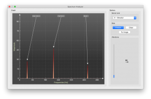
El analizador de espectro es una herramienta para medir la cantidad de vibraciones en su modelo. Es una herramienta de diagnóstico diseñada para determinar qué parte giratoria está causando un problema. Con esta información usted puede fácilmente identificar y solucionar los problemas con su modelo.
To check condition of the model you can see "Vibrations" bar. This indicate general vibration amplitude in selected axis.
Es posible medir las vibraciones en tres ejes separados:
- X - elevator axis (elevador)
- Y - aileron axis (aleron)
- Z - rudder axis (cola)
- In-Flight - flight vibration player
El gráfico muestra las frecuencias en vivo para el eje seleccionado. Esto le permite ver tanto la frecuencia y la magnitud de la vibración en el eje seleccionado.
Las vibraciones se transmiten a cada uno de los ejes depende de varios factores, distintos. Frecuencias y magnitud dependen de la construcción del modelo. En general, las vibraciones son las más altas en el eje Y (alerones), pero le recomendamos que revise todos los ejes, cada vez que usted está haciendo la medición. Sin embargo vibraciones no deben exceder de 50% para todos los ejes en cualquier momento. En el caso de vibraciones están en 90% o más, el modelo tiene un problema que necesita ser corregido. En caso de que la magnitud superior al 90% en cualquiera de los ejes dados, se recomienda fijar cualquier problema que está causando estas vibraciones extremas antes de volar el modelo. A pesar de que la unidad de Espíritu FBL es altamente resistente a las vibraciones, éstas podrían causar interacciones no deseadas con la unidad de Espíritu FBL y también podría causar una falla mecánica del modelo. Tales vibraciones de alta pueden causar un fallo u otras partes mecánicas para romper.
Niveles de vibracion:
- Vibraciones mas de 50% - niveles de vibracion aceptables y normales
- Vibraciones entre 50% y 90% - niveles elevados de vibraciones
- Vibraciones que excedan 90% - niveles de vibracion extremas
Así como los niveles de vibración en general no superior a 50%, cualquier frecuencia específica (pico) no debe exceder de 50%. Cualquier cosa por encima de este nivel debe ser motivo de preocupación y requiere mayor investigación.
Para la comparación de los gráficos, puede utilizar el botón de congelación. Se muestra el gráfico en vivo actual y el gráfico capturado usando el botón Freeze se guarda y se mostrará como subgrafo. Este gráfico se puede borrar con el botón Clear.
Es posible guardar las gráficas del analizador de espectro. Utilizando el botón To image, el gráfico actual se guardará como una imagen.
El analizador de espectros es capaz de detectar las frecuencias de vibración de hasta 500 Hz (partes que gira a velocidades de hasta 30.000RPM).
'Procedimiento de medicion.'
- Retire principal y de cola palas del modelo.
- Coloque el modelo en una superficie adecuada, suave (por ejemplo, la alfombra, hierba).
- Conjunto de paso de pala de aproximadamente 0 ° a ambos principal y de cola rotores.
- Ejecutar el analizador de espectro (esto también se queda como todos los servos).
- Girar el motor a la RPM de vuelo habitual.
- Cambie entre los ejes X, Y y Z, guardar una imagen de cada uno.
- Verifique vibraciones en todos los ejes.
- Pare el motor.
Reconociendo las vibraciones
Reconocer qué componente o parte está causando vibraciones anormales es necesario para determinar la velocidad de los picos más altos. El rotor principal tiene la velocidad más baja y la velocidad del rotor de cola será de aproximadamente 4.5x más alto. En general, cuanto menor es el tamaño del modelo, mayor es la velocidad de la cabeza será.
Con el fin de averiguar qué parte del modelo está causando las vibraciones no deseadas, mover el cursor a la cima y comprobar la velocidad de la cabeza (RPM). La velocidad del rotor principal es usualmente en el rango de 1500 a 3500 RPM. Por lo tanto, si la velocidad está dentro de este intervalo, es probable que hay un problema con el engranaje principal, eje principal, los cojinetes del eje principal o cabeza de rotor en sí.
La mayoría de las vibraciones excesivas suelen ser, aunque no siempre, relacionado cola. Para comprobar si hay vibraciones procedentes de la cola que debe encontrar el pico de frecuencia que es aproximadamente 4.5x mayor que la frecuencia del rotor principal.
Una vez que identifique qué parte del helicóptero está causando las vibraciones no deseadas, puede eliminar gradualmente los componentes del conjunto sospechoso, repitiendo el proceso de medición hasta que la vibración desaparece. Una vez que los niveles de vibración se han reducido a un nivel aceptable, usted ha encontrado el componente sospechoso y puede reemplazarlo.
Medición con hojas de cola instalado conlleva algunos problemas de seguridad y también mostrará un aumento de los niveles de vibración.
NOTA
Motores Gasser no deben ser operados sin carga! Medición de vibraciones no se puede realizar sin cuchillas.
In-Flight - vibration analysis from flight
This feature allows you to record vibration spectrum from any moment of the flight. By selected channel you can tell the unit when the spectrum should be taken. The spectrum can be later viewer in the Spirit Settings software with the In-Flight option in the Diagnostic/Spectrum analyzer. Saved vibration spectrum will be stored until unit will lost the power. Saved record is rewritten on repeated activation.
For vibration measurement in the flight set the Special function in the General/Channels. Assign function F: Vibration analysis with axis you want to measure. Then select a channel which will be used for activation of the function.
As soon as the value is equal to 1 the vibration spectrum is saved. The record is saved exactly at the moment when function will change it's state from 0 to 1.
During flight it is enough to change state of selected switch of your transmitter (for example 2-state switch). After landing you can connect unit with the software and open the Vibration analyzer (select In-Flight axis to display the spectrum).
BEC TESTER (TESTEADOR DE BEC)
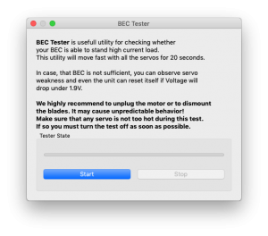
El probador se utiliza para determinar si la fuente de alimentación es para la unidad, el receptor y los servos suficiente. El propósito es lograr el mayor pico de corriente y comprobar que la tensión de alimentación no caerá bajo el nivel seguro.
Haga clic en el botón Start (Inicio) para iniciar la prueba. Después de 20 segundos debería estar terminado. Si va a observar cualquier problema, cuando su fuente de alimentación es insuficiente y no se debe utilizar. En este caso, la fuente de alimentación con una mayor capacidad de corriente debe utilizarse.
LOG VIEWER (REGISTRO DE VUELO)
El registro se usa para grabar eventos durante el vuelo. Si se produce un problema y la razón es que no conoce o evidente de inmediato, comprobando el registro puede ayudar a identificar el problema.
Funciona de tal manera que registra varios eventos desde el momento en que la unidad está encendida. Si se produce un evento se puede ver esto en el registro, la presentación de informes en el registro se lleva a cabo cada 10 seg. Al hacer clic en el botón de registro abierto se puede ver el registro de vuelo actualizado que contiene todos los eventos del último vuelo. Cuando se desconecta la alimentación, el registro se borra.
En el caso de un problema importante que ocurra durante el vuelo ![]() la de registro se guarda de forma permanente en la memoria de la unidad y permanece allí hasta el momento en que se abre el registro. Si existe un registro guardado en la memoria, al usuario se le advierte con el mensaje "Registro de vuelo anterior está disponible!" Y el registro de vuelo, cuando se produjo el problema se abre. Por ejemplo, cuando una señal se
pierde o la fuente de alimentación no se puede encontrar esto en el registro. El registro del primer vuelo donde se produjo el mayor problema está siempre salvado. Si esto no se abre, entonces no va a ser sobrescrito por uno más nuevo. En este estado, el usuario también es notificado por diferentes movimientos del paso cíclico durante el proceso de inicialización.
la de registro se guarda de forma permanente en la memoria de la unidad y permanece allí hasta el momento en que se abre el registro. Si existe un registro guardado en la memoria, al usuario se le advierte con el mensaje "Registro de vuelo anterior está disponible!" Y el registro de vuelo, cuando se produjo el problema se abre. Por ejemplo, cuando una señal se
pierde o la fuente de alimentación no se puede encontrar esto en el registro. El registro del primer vuelo donde se produjo el mayor problema está siempre salvado. Si esto no se abre, entonces no va a ser sobrescrito por uno más nuevo. En este estado, el usuario también es notificado por diferentes movimientos del paso cíclico durante el proceso de inicialización.
El registro puede contener los siguientes eventos:
![]() Good Health Message (mensaje Buena Salud):
Good Health Message (mensaje Buena Salud):
- El modelo se encuentra en buenas condiciones. La unidad no reconoció ningún problema.
-
![]() Calibration Finished (Calibracion terminada):
Calibration Finished (Calibracion terminada):
- La calibracion del sensor se ha realizado correctamente.
-
![]() Governor was Engaged (Governador se Comprometio):
Governor was Engaged (Governador se Comprometio):
- Governador logro RPM solicitado y esta activo desde este momento.
-
![]() Cyclic Ring Activated (Cyclic Ring Activado):
Cyclic Ring Activated (Cyclic Ring Activado):
- Cíclica alcanzó su máximo ángulo de inclinación. Esto indica que el modelo era incapaz de hacer la corrección deseada según sea necesario. En la mayoría de los casos no es relevante. Pero es posible que el valor del parámetro de cyclic ring es demasiado baja y el modelo no puede girar tan rápido como se pretende en los ejes de alerones/elevador. Alternativamente, un valor demasiado alto para la velocidad de rotación puede ser configurado. También es posible que en vuelo de avance rápido el modelo puede lanzar en marcha rápidamente. Se recomienda establecer este parámetro tan alto como mecánicamente posible.
-
![]() Rudder Limit Reached (Limite de Timon Alcanzado):
Rudder Limit Reached (Limite de Timon Alcanzado):
- El servo del timón alcanzó su límite configurado. Cuando este evento se produce antes o después de un vuelo no es un problema. Si ve este durante el vuelo indica que el timón no funciona correctamente. En la mayoría de los casos es visible durante el vuelo como mala respuesta del timón o "apagar". Si el modelo se ha configurado correctamente, entonces podría ser debido a la baja eficiencia del timón, como las hojas de cola es demasiado corto o la velocidad de la cabeza demasiado bajo. También existe la posibilidad de un problema mecánico o con los límites de timón siendo insuficiente.
-
![]() RPM Sensor data are too noisy (Datos del sensor RPM son demasiado ruidoso):
RPM Sensor data are too noisy (Datos del sensor RPM son demasiado ruidoso):
- Lectura RPM es muy inestable y es oscilante más de +/- 100 RPM. Los datos del sensor son inservibles para el Gobernador. Utilice blindaje adicional y montar un anillos de ferrita. Aumentar valor del parámetro de filtro Sensor RPM.
-
![]() Received Frame was Corrupted (Trama Recibida fue Dañada):
Received Frame was Corrupted (Trama Recibida fue Dañada):
- Trama recibida es inutilizable y se ignorará. En las mayoría de los casos no presenta ningún problema. Si el evento se produce a menudo, entonces la conexión entre el receptor puede estar equivocada o hay exceso de ruido. Verificar la calidad del enlace y compruebe el cable entre la unidad y el receptor.
-
- Sensor data reading failed - RPM sensor malfunction probably occured. Sensor is not sending data for 2 seconds or longer. Make sure, that the sensor wiring is correct and that the motor is spinning when Hold is disarmed.
-
![]() Receiver Signal Lost (Señal Receptor Perdida):
Receiver Signal Lost (Señal Receptor Perdida):
- Señal se perdió repentinamente. Este problema no debería ocurrir en cualquier momento y debe ser resuelto antes de próximo vuelo. Podría haber un problema con el receptor y/o antenas transmisoras. Podría ser un cable del receptor defectuoso o la conexión entre la unidad y el receptor. En algunos casos la señal de pérdida puede ocurrir debido a una descarga electrostática causada por la acumulación estática, esto ocurre generalmente en helicópteros accionados por correa.
-
![]() Main Loop Hang Occurred (Caida Bucle Principal Ocurrio):
Main Loop Hang Occurred (Caida Bucle Principal Ocurrio):
- El bucle principal se retrasó. Esto puede suceder cuando el cableado no es correcta o hay interferencia anormal ruido eléctrico con la unidad, por ejemplo, de un BEC. Si se utiliza el software de configuración podría significar el enlace a la unidad de Espíritu FBL es más lento de lo que debería ser.
-
![]() Power Voltage is low (Poder de Voltaje Bajo):
Power Voltage is low (Poder de Voltaje Bajo):
- Tensión de alimentación es inferior a 2.9V. Esto significa que usted tiene que usar 0 un BEC que es capaz de manejar cargas más altas. En casos raros podría ser conexiones defectuosas en los cables.
-
![]() Vibration Level is very high (Nivel Vibracion es muy alto):
Vibration Level is very high (Nivel Vibracion es muy alto):
- Nivel de vibración alcanza el nivel que no es normal y puede afectar a la integridad del helicóptero. Durante las maniobras 3D duro el evento puede ocurrir con más frecuencia.
-
Todos los registros revisados se guardan como archivos PDF en el directorio Documentos.
5.4 SERVOS TAB (FICHA SERVOS)
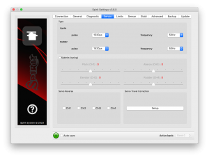
Esta ficha se utiliza para la configuración del servo, se debe tener cuidado para asegurarse de frecuencias correctas se utilizan y que las direcciones se establecen correctamente.
Tipo
En esta sección, establezca los valores de pulso neutro y frecuencia de acuerdo a sus especificaciones del fabricante servo.
Para servos analógicos la frecuencia es por lo general un máximo de 60 Hz.
Subtrim (tuning)
Idealmente, sin la cabeza del rotor instalado, utilice un nivelador oscilante para alinear los cuernos oscilantes de servo de manera que los cuernos del
plato ciclico y servo son horizontales y perpendiculares al eje principal. Esto se hace marcando el elemento Sub Trim (tuning). Esto pondrá la unidad Spirit FBL en un modo especial en el que la posición colectiva será neutral con los servos centrados. Además, se desactivará la estabilización. Servos se pueden ajustar fácilmente en este momento. Cuando se haya completado, el plato cíclico debe ser exactamente perpendicular al eje
principal y, además, el paso colectivo debe estar a 0 ° (es posible medir el ángulo de paso utilizando un medidor de paso con la cabeza del rotor y palas adjunto).
En la mayoría de los casos, también es necesario para cuernos servo para ser perpendicular al eje principal. Todos los servos, es decir, CH1, CH2, CH3 y CH4, se establecen por separado en deslizadores individuales. CH1 y CH3 son los servos de alerones. CH2 controla el elevador y CH4 controla el timón.
También es necesario para establecer el ajuste sub y la mecánica del timón de manera que el servo cuerno es perpendicular a su caso y el tono del timón es a 0°. Este ajuste afectará el rendimiento de parada timón.
Una vez configurado, quite la marca de la casilla de verificación Subtrim (tuning) para desactivar este modo especial.
Después de salir del modo especial, la estabilización y el timón funcionará de nuevo. Asegúrese de que su canal de paso colectivo está configurado correctamente en el transmisor. Eso significa que usted debe ver a -100% a 100% de la ficha de diagnóstico. Verifique que 0% en la ficha de diagnóstico corresponde con la posición media de su stick colectiva/acelerador (con lineal -100% - 100% curva de paso).
Servo reverse (Reverso servos)
Esto le permite elegir qué servos deben tener su dirección de movimiento invertido. Si bien el cambio del paso colectivo ,todos los servos deben moverse en la misma dirección. Después de esta configuración el modelo debe reaccionar correctamente al movimiento palos.
Este parametro es el mas importante!
Servo travel correction (correccion recorridos servo)
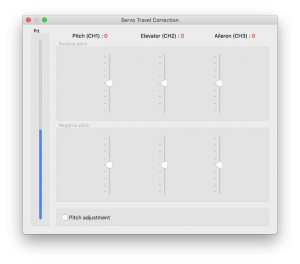
Aquí, usted es capaz de modificar recorrido correcto para cada servo individualmente. Algunos servos no son muy precisos en cuanto a recorrido a sus límites y esta imprecisión pueden tener un impacto negativo en las características de vuelo. Una vez en esta sección del software, la unidad cambia a un modo de hacer estas correcciones.
Se espera que en el paso anterior, Subtrim (tuning), la placa oscilante se fijó en cero colectiva (0° rotor palas de paso). El procedimiento es tal que debe usar un nivelador oscilante para determinar si hay alguna desviación en cualquiera de los servos en los puntos más bajos y más altos de tiro colectiva. Para las posiciones tanto positivos como negativos, es necesario establecer por separado los valores - esta es la razón por 6 deslizadores. Si el recorrido es menos de lo necesario, aumente el valor. Si demasiado, disminuya. Para activar controles deslizantes en la parte secundaria mover el colectivo de dirección opuesta.
Esta corrección también es útil si hay geometría asimétrica en el helicóptero causando problemas tales como la incapacidad de lograr valores positivos y negativos igualdad de tono. En este caso, es necesario modificar los deslizadores positivos o negativos para los tres servos. Si no está seguro acerca de la configuración, es mejor dejar los controles deslizantes en el Oriente. (posición 0)
5.5 LIMITS TAB (FICHA LIMITES)
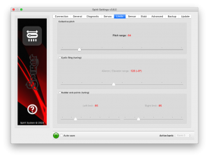
Esta ficha afecta límites y rangos de recorrido de servo.
Cyclic Ring (tuning) (Anillo Ciclico)
Este parámetro establece el anillo cíclico electrónico, que permite que el modelo para lograr las mayores gamas cíclicos sin unión mecánica (la unión de cuernos servo, varillas de empuje y los vínculos). Este parámetro actúa como un denominado anillo cíclico electrónico.
Estos ajustes deben hacerse con mucho cuidado para evitar daños en el modelo y sus componentes electrónicos asociados.
En primer lugar, establecer su rango colectiva deseado, por ejemplo, +/-12°. Se recomienda utilizar una curva de paso lineal -100% a 100% en el transmisor. Ahora es el momento de establecer el rango de tono cíclico máximo Aileron/Ascensor. Trate de establecer la mayor desviación posible.
Este parámetro no afecta directamente a la velocidad de rotación, pero si es demasiado bajo, el modelo no puede tener tasas de cabeceo y balanceo consistentes.
Este ajuste se debe hacer con 0 ° paso colectivo. Luego revise cuidadosamente máxima deflexión palo en todas las direcciones para asegurarse de que la unión mecánica no ocurre. Esto debe también entonces hacerse con el máximo y el mínimo paso colectivo. Este parámetro actúa como un denominado anillo cíclico electrónico.
If you increase the collective pitch range, this parameter must then be checked and in some cases adjusted to insure no binding occurs at your new maximum and minimum pitch ranges. If the selected cyclic ring range is insufficient, it is possible that pitch-up can happen during fast forward flight (even if the pitch-up compensation is at its maximum value). This is because the model will not be able to add sufficient corrections with the configured range.
Rudder end-points (tuning) (Puntos finales cola)
Left / Right limit - Sets the minimum and maximum deflection of rudder rotor blades.
SENSOR TAB (FICHA SENSOR)
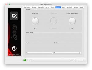
5.6 SENSOR TAB (FICHA SENSOR)
Esta pestaña es la parte ultima importante de los ajustes que se deben configurar.
Sensitivity (Sensibilidad)
El dial giratorio ajusta la sensibilidad del giróscopo para ejes de alerones, profundidad y dirección.
Cyclic gain (Gnacia ciclico) – Cuanto más alto sea el valor, mayor será la precisión dentro del bucle de control. El valor predeterminado es pre configurado para 55% de ganancia, para la mayoría de los modelos se sugiere un valor óptimo de alrededor del 60%.
Rudder Common Gain (Ganacia de Cola Comun) – 100% significa que no hay multiplicación. Este es el valor recomendado para helicópteros 550 de clase y más pequeño. Para helicópteros más grandes a menudo es más alto. 130% podría estar bien. Transmisor ganancia del giróscopo debe configurarse para aproximadamente el 60% para el primer vuelo.
Rudder Gain (Ganancia Cola) – Este parámetro sólo se activa en caso de canal de ganancia Gyro sin asignar. Sustituye a la función de la ganancia Gyro desde el transmisor, lo que puede establecer directamente el valor en el software.
Ganancia de timón en el software o en el transmisor puede ser programado de esta manera:
- Head-Lock mode(modo bloqueo cola): 1% to 100%
- Normal(Rate) or a special function (sin bloqueo cola o funcion especial): -100% to 0%
Ganancia del giróscopo negativo se puede utilizar para activar el rescate de los modos de estabilización - compruebe la pestaña Stabi.
Rychlost rotace
Výchozí hodnoty by měly vyhovovat spíše začátečníkům, model by se měl chovat líně, avšak tento faktor závisí také na mechanickém přepákování, popř. D/R (Dual Rate) funkci vysílače a parametru Rozsah Křidélka/Výškovka v záložce Serva.
Větší hodnota znamená větší rychlost rotace.
default value - 8
We recommend to set the Cyclic rotation rate within a range of 8 - 11. Remember that DFC rotor heads tend to rotate faster so it's better to initially start with a lower value for them.
For the Rudder rotation rate pilots are preferring a range of 9 – 11.
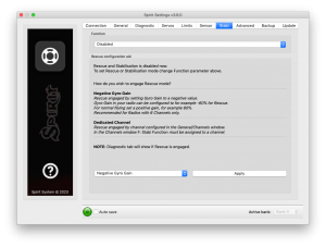
5.7 STABI TAB (FICHA ESTABILIZACION)
La unidad Espíritu te ofrece las opciones de modelo de estabilización y el modo de rescate. La función de estabilización, una vez activado, recuperará el modelo a una posición horizontal sin ninguna otra entrada del piloto, este puede ser utilizado como una característica de "rescate" al intentar nuevas maniobras y puede ayudar con el proceso de aprendizaje.
El modo de rescate complementa la operación normal de la unidad Spirit. De activado, el modelo se recuperará a una posición horizontal y añadir paso colectivo según la configuración. Esta función se puede utilizar en cualquier momento cuando el piloto pierde la orientación o el control del modelo.
La unidad Spirit le permite asignar un modo de estabilización o de rescate mediante el canal de ganancia del giróscopo. De 0 - 100% en el transmisor está siempre diriguido al modo de giróscopo bloqueo cola y con -100 - 0% de ganancia, son capaces de activar la estabilización o el modo de rescate. Esto significa que en lugar de modo normal (tasa), permanecerá en la partida modo de retención giroscopio, además de rescate/estabilización se activa. Así, mientras que el modo de rescate/estabilización se activa, una ganancia del giróscopo de -70% se considera un 70%. Este comportamiento también se puede observar en la ficha Diagnóstico.
Algunos transmisores tienen un rango de 0 a giróscopo 100% donde el 50% es el medio - ganancia de cero (por ejemplo, Spektrum DX6i). Otros usan un rango de -100% y 100%, donde 0% es el medio.
Funkce
Here is where you select which mode should be activated at negative gyro gains.
Disabled - Normal (Rate) gyro mode.
Rescue (Normal) - Recovers the model to an upright horizontal position – skids always to the ground. This recovery mode is great for the beginners.
Rescue (Acro) - Recovers the model to a horizontal position, inverted or upright, whichever is closer at the time of activation. For intermediatte and advanced pilots that are flying acrobatic manouvers.
Stabilization (Normal) – stabilization mode - skids always to the ground. This mode is good for learning the basics such as hovering and slow transitions. Model is always pushed to the horizontal position.
Stabilization (Acro) – stabilization mode - inverted or upright, whichever is closer at the time of activation. This mode is used for learning the basics of acrobatic maneuvers. If the sticks are in the center, the model has tendency for returning to the horizontal position.
Stabilization (Scale) – stabilization mode - skids always to the ground. This mode is used for a scale flying. Gyro mode is Normal (Rate).
Coaxial – stabilization mode - inverted or upright, whichever is closer at the time of activation. The steering behavior is very similar to a coaxial helicopters. Great for learning a hovering practices.
If using these modes, be sure your helicopter is initialized on a flat surface, not tilted to any side. Do not tilt the helicopter for more than 5 seconds.
The rescue mode is very demanding on the BEC. Be sure your BEC can handle such peak loads. In case it is is not sufficient your model could crash! Never exceed angles recommended by manufacturer of the model, else the mechanics can be damaged during the flight!
Flybar mechanic
If your helicopter is equipped with traditional flybar mechanics, you have to enable this parameter in order to use the stabilization or rescue modes. All settings are the same for flybarred helicopters except this parameter.
Flybarless helicopters must be configured and operated with the Flybar mechanic parameter disabled!
Rescue collective pitch
This determines how quickly the model will recover to a horizontal position.
100% means the maximum deflection of the blades, which was configured in the Servos tab.
It is very important to check whether the rescue mode works correctly before the first flight (on the bench without the motor/rotors running).
Collective pitch should be always positive with the rescue engaged - while helicopter is on the ground
Sticks priority
Specifies the amount of control while configured mode is activated.
The higher the value, the more the model will react to stick movements.
Direction control rate
This specifies the rate of controlling direction for the stabilization mode.
Low values are well suited for beginners to get coaxial like behavior. Higher values are more appropriate for scale flying.
Acro Delay
Specifies a time period for the Rescue (Normal), when the model is recovered from the inverted flight. Until the period is reached, the rescue has the same behavior as the Rescue (Acro). In this way, faster ascending to a safe level can be achieved.
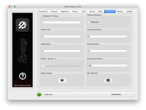
5.8 ADVANCED TAB
This tab is for more advanced configuration of the Spirit FBL unit. It is recommended that you fully understand these parameters before adjusting them. However, it is essential to set geometry. Other parameters, however, depend on the preferences of the pilot.
Geometry 6° (tuning)
For proper operation of the Spirit unit, it is necessary to set this parameter correctly. Here, the unit is switched to a special mode for settings 6° of cyclic pitch on the main blades. It is necessary to set the value so that the blades angle is at 6° in the aileron axis. You need to rotate your rotor head with blades to be parallel to the longitudinal axis of the model. A higher value increases the angle; a lower one decreases the angle. Optimal head geometry should be in the range of about 90 – 160. If not in this range, it is recommended to adjust the distance of a ball link on the servo horns or perform other mechanical adjustments.
Collective Direction
Parameter to determine direction of the collective pitch.
In case of a Trailing Edge rotor head or if a mixing arms are present on the rotor head, tick the Reversed option. In the most cases the parameter is unticked.
Correct configuration is very important, else the collective pitch will be reversed.
Elevator filter
This parameter compensates elevator bouncing during aggressive maneuvers. The larger the value, more compensation is involved.
If this value is too high it can lead to a soft feeling in the elevator. We recommend using the default value of 1 to begin with.
Cyclic feed forward
This parameter is used to set amount of direct feel between your sticks and
your model helicopter. The higher the value, the more aggressive the model
will feel and the faster the model will react to stick movements.
If the value is very high, elevator bounce-back effect can occur.
During a tic-toc maneuver you can also observe higher motor load or aileron oscillations, because the model is unable to react fast enough.
Setting this value too high can result in elevator bounce.
If the model feels disconnected and there is a lag between stick inputs and
the model, try increasing this value.
Rudder delay
This is a parameter to smooth rudder movements. It also helps to stabilize the rudder – it is a kind of electronic damping. The faster the servo is, the lower the tail delay should be. For analog servos it is recommended to set this value to around 20-25. For usual digital servos it is mostly between 10 – 15. For very fast servos (~0.04s/60°) the value is 5. In case of a brushless servos it is recommended to set a value of 0 - 2.
If the value is too high, the rudder could start to oscillate or wag or could cause a slow rudder stop.
Rudder dynamic
If the rudder does not stop correctly, for example it overshoots, this behavior can be changed with this parameter.
6 – is the default value.
The larger the value, the more aggressive the behavior of the tail. If the tail overshoots in stops, the value is too high. This parameter also affects the response speed of the stick movement; a higher value means a faster response. If you cannot reach a symmetric stop on both sides you will need to make sure that the tail is centered at 0°. Alternatively, you can lower the rudder limit for that side.
Rudder – Revomix
Revomix (tail pre-compensation) adds rudder in response to collective pitch changes, when the tail needs increased holding. Revomix is independent of the transmitter. By default it is turned off, the user must set the amount required of the pre-compensation.
Allowed values are 0 to 10 with 0 being disabled; in most cases it is not necessary to use this parameter, however, when using low headspeed or on helicopters with a poor performing tail, this setting can be used.
Pirouette consistency
This parameter determines the consistency of pirouettes and holding performance. If pirouettes are not consistent during certain maneuvers, increase the value of this parameter.
This value is individual for every model, it depends on many factors such as: your rudder mechanics, head speed, etc. Before setting this parameter, it is recommended to first set the gyro gains.
If the value is too high, the tail can oscillate or wag. It can also cause poor stop performance. This value should be between 150 and 180.
For brushless servos it is recommended to increase value by 10-15 points.
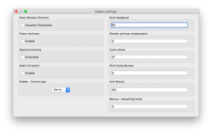
EXPERT SETTINGS
For fine tuning you can set the following parameters. Normally it is not needed to configure any of these parameters.
Rotor Rotation Direction
Parameter to determine rotation direction of the main rotor. In the most cases it is in the clock wise direction - parameter is unticked.
Stick deadband
Determines the area, around center stick, where the system does not recognize any stick movement. If channel readings are inprecise the value should be increased. This can be verified in the Diagnostics tab. This parameter does not replace the Exponential function.
Elevator pitchup compensation
If, during fast forward flight, the model reacts to inputs too rapidly or if the model pitches up, increase this value until this no longer occurs. If the helicopter pitches up abruptly, this could be caused by a cyclic range that is too low and/or too much collective pitch. In this case, you will have to increase the Aileron/Elevator range as high as the model can handle without any binding. If this doesn't fix the problem, you can add more pitch-up compensation.
Cyclic phase
The value indicates the angle by which the swashplate is virtually rotated.
For example a value of 90 will rotate the elevator to aileron. This feature is recommended for models with multi-blade rotor heads. For most other models, we recommend a zero value.
Pitch Pump Booster
To achieve flybar-like collective pitch behavior, you can increase the value until desired feeling is achieved. Remember that higher values are too demanding for power supply and servos on the model.
Signal processing
This parameter is used for operation on models with extreme vibrations that can't be eliminated in any way. This should be enabled only in cases when is absolutely necessary, because flight performance could be affected. It should increase precision of flight and also the precision of rescue and stabilization modes.
RPM Sensor Filter
In case that your RPM sensor has noisy output then RPM readout can be very unstable. This can lead to various problems with Governor. There may be a problem with spool up, flight mode switching or head speed jittering. To make RPM readout very precise, you may need to increase the value.
On the other hand, too high value can lead to a delay, that is unwanted for optimal Governor performance. So the value should be as low as possible while RPM readout is still precise. Variation of 1-20 RPM against the Requested RPM is optimal.
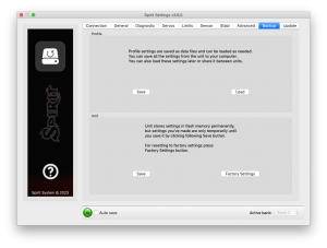
5.9 BACKUP TAB
Here, you can save the settings to your Spirit unit before powering off, you can also save the settings to your computer here, Should you need to reload them at a later date.
Profile
This section allows you to Save and Load complete settings of the unit to a specified file. If you have more than one of the same model, it is not necessary to carry out a complete setup again, just load the stored settings easily with the Load button.
Unit
Any changes to the configuration can be saved at any time to the internal flash memory of the unit.
To put all settings to a factory defaults, click Factory Settings.
Remember to save the settings each time you want to store the settings permanently. You must press the Save button. Otherwise, the changes will be lost after the Spirit FBL unit is turned off.
Bank Switching
In case that the Bank Switching is enabled, you can save the settings from single bank or even all banks. To see the differences between Banks you can use Bank Comparison feature.
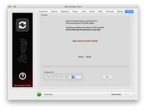
5.10 UPDATE TAB
If you want to update the firmware, you can do so in this tab.
Firmware
First select the data file containing the firmware (*.4df) – Select button.Once the file is selected, press the Flash button. The upgrade progress will be displayed here. After completion, a confirmation dialog box should indicate a successful update.
Then, unplug the unit from its power source.
Upon the next start it will load with the newly flashed firmware.
Configuration of the unit is not changed, so you do not need to save/load it.
You can get firmware from: spirit-system.com.
6 BANK SWITCHING
This functionality allows you to switch between saved settings during a flight. Switching is done through the transmitter, so that channel's value is changed. This mean that a Bank can store one unique settings. The unit is able to store 3 different banks.
With a transmitter you are able to use a three position switch to switch freely between banks.
Bank switching is disabled by default, so you can decide whether it is useful in your application. You have to activate it by the assignment of Bank function in the General/Channels window. Generally, it is assigned to channel 7.
Bank 0 – active in range of lower third (impulse under 1400μs).
Bank 1 – active in range of mid third (impulse between 1400μs to 1640μs).
Bank 2 – active in range of upper third (impulse above 1640μs).
Initial settings for Bank 1 and Bank 2 are equal to Bank 0. Bank 0 allow you to configure all parameters, while Bank 1, 2 does not allow to set main parameters. For safety, Bank 1 and 2 does not allow you to set any main parameters.
The Bank switching is great for switching between flight styles, sensor gains for low or high RPMs, for slow acro or 3D. Alternatively it can be used just for tuning your settings.
If the software is connected with the unit then bank switching via the transmitter is disabled. Then, Bank switching is performed using the software in bottom part of the window. When a bank is switched using the software it is necessary to save your settings to the unit before you switch Banks, or your settings will be returned to the previous (unchanged) state.
7 GOVERNOR
From firmware version 1.2 governor feature is available! You can use this feature instead of internal governor from your ESC or other governor. It is designed to work with electric, nitro and gasser helicopters. This can make flight performance even better because of constant head speed.
To achieve proper function it is very important to configure your ESC and then the unit. First from all make sure that internal governor is disabled in the ESC.
It is necessary to disassemble rotor blades from your model prior to the governor setup. Do not make any adjustments with motor turned on.
Governor feature can be used with the following receiver types:
Spektrum DSM2/DSMX, Futaba S-BUS, Jeti EX Bus, SRXL/SUMD.
It is necessary to use throttle output from the unit when using governor. Throttle output is at the AUX port. You must connect the ESC or throttle servo there.
7.1 Sensor Wiring
Signal from a RPM sensor should be connected to the PIT pin (middle pin of the ELE/PIT/AIL port).
- ESC with RPM output
- For electric helicopters the best and the easiest solution. You can use RPM output cable that is present on the ESC.
- ESC without RPM output
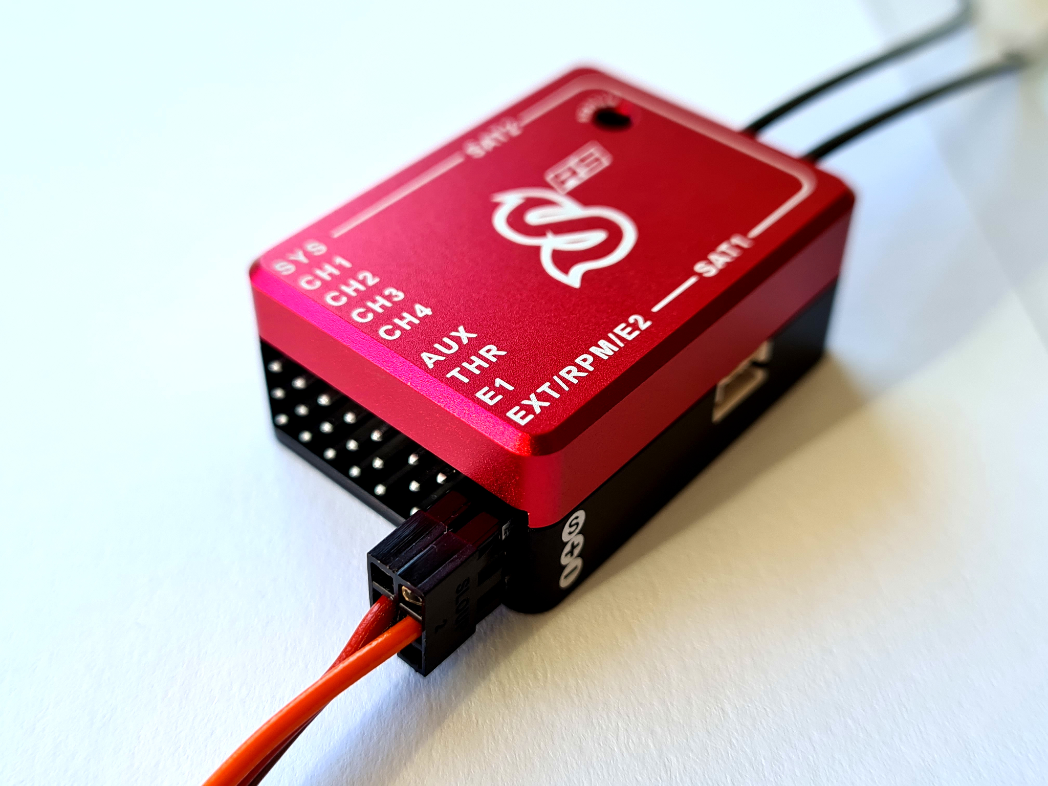
- In case that your ESC has no RPM output you will need a separate RPM sensor that can be connected to phases of the motor. Important is to power the sensor properly. Voltage can't exceed allowed level for the sensor. Recommended voltage range can be obtained from the sensor manufacturer. In case that the sensor require 3.3V you can connect it to the satellite connector in the unit (Details in the following photo). You can also use the Spektrum adapter.
- In case that the sensor is powered improperly it can be damaged along with the unit.
- Magnetic sensor
- In case that your ESC has no RPM output you will need a separate RPM sensor that can be connected to phases of the motor. Important is to power the sensor properly. Voltage can't exceed allowed level for the sensor. Recommended voltage range can be obtained from the sensor manufacturer. In case that the sensor require 3.3V you can connect it to the satellite connector in the unit (Details in the following photo). You can also use the Spektrum adapter.
- In case that the sensor is powered improperly it can be damaged along with the unit.
Red (+3.3V), Brown (GND).
7.2 Prerequisites
Electric
- Set throttle range in your transmitter so that 0% and 100% throttle position matches with value of the throttle bar in the diagnostics tab. This can be done by Subtrim function in your transmitter and/or Travel Adjustment function.
- Re-calibrate throttle range according to instructions of your ESC. In the most cases it can be configured by powering the model with throttle stick with 100% throttle and then by moving the stick down to 0%.
- If possible, configure fast spoolup mode in the ESC so the governor will be unaffected.
Nitro / Gasser
- Set the throttle range in your transmitter so that 0% and 100% throttle position matches with value of the throttle bar in the diagnostic tab. This can be done by Subtrim function in your transmitter and/or Travel Adjust function.
7.3 Activation
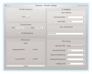
To activate Governor feature in the unit, you will need to assign Throttle function in the General tab/Channels. Then you will be able to enter Governor Settings in the General tab.
7.4 Settings
First from all basic settings are necessary so the governor can control the head speed correctly.
Throttle frequency
To achieve the fastest governor reaction it is necessary to set the highest possible frequency. For ESC it could be only 60Hz, but mostly all can work even with 200Hz. If you are unsure, please contact manufacturer of the ESC. For combustion helicopters it is max. operating frequency of the throttle servo.
Throttle Range
This parameter can affect output from the unit so you can fine-tune ranges precisely. For electric helicopters this parameter is optional. But in case that your ESC does not allow to calibrate throttle range correctly, you can do so here. For Nitro and Gasser helicopters you have to configure it always so the Throttle servo range matches range for the motor.
Throttle Range - Min.
Value of the lowest throttle signal. Default value: 1100 μs. For electric helicopters this value should be specified by manufacturer of the ESC. It is often specified in value of miliseconds (ms).
You should set the lowest position when the motor is not spinning up anymore – is halted. While configuring this, the motor can start so you have to be very carefull.
Throttle Range – Max.
Value of the highest throttle signal. Default value: 1900 μs. For electric helicopters this value should be specified by manufacturer of the ESC. It is often specified in value of miliseconds (ms).
The value should be configured to match with 100% throttle output programmed in your ESC or full throttle of the motor. If this parameter is not high enough you will be unable to tune Governor because there will be not enough room to compensate high loads. If configured too high then you can observe that after high load head speed will not drop immediately but can be there even for few seconds. When Min. parameter is changed it is also necessary to update this one.
Throttle Reverse
Especially for Nitro and Gasser motors you can set correct compensation direction for the servo here.
Gear Settings - Sensing Divider
Electric motor: Motor poles / 2. For a 10 pole motor set divider to number 5. Mostly configured to 3 – 5.
Nitro/Gasser motor: Number of all active magnets. Mostly it is 1 – 2.
Gear Settings - Gear Ratio
Gear Ratio of the helicopter between the main wheel and pinion of the motor. For example: 120T main gear / 12T pinion = 10.
Max. Head Speed
Configure max. head speed that should be achieved with 100% throttle curve. For example: If you know that you won't exceed 2500 RPM then you can set the value to 2500. With 80% throttle curve your head speed will be 2000 RPM (2500 * 0.80 = 2000).
Fine-Tuning – Spoolup rate
Configure speed of the motor spoolup. For initial tests we recommend Slow spoolup rate.
Fine-Tuning – Spoolup Rampup
Value that will be added at the beginning of motor spoolup – when Hold is turned off. If the spoolup is not smooth, i.e. motor will start with a kick, the value is too high. If the spoolup has a delay, the value is too low. Default value of 50 μs should work fine in the most cases.
Fine-Tuning - Governor Response
This parameter is the most important one to achieve fast and proper response of the governor. It determine how fast the governor should react to a short-term load. Thus optimal settings are required. If configure too low or too high, rudder will not hold properly and can oscillate. Governor can greatly affect rudder performance so you can achieve better holding behavior. Too high value will result in overspeeding during e.g. pitch pump.
Fine-Tuning - Holding Performance
Determine how well the head speed is maintained during a long-term load. If value is too low then during e.g. tic-toc maneuver head speed can drop gradually. In case it is too high then after the tic-toc head speed can be higher than necessary and can even return to requested RPM with noticeable delay. It is better to start governor tuning process with low value.
7.5 Fine-Tuning Procedure
Firstly you have to finish basic setup including Max. Head Speed. Throttle curve in the transmitter must be FLAT. We recommend to set the throttle curve for example to flat 70%, 80% or 90%.
After disarming Throttle Hold you should immediately see Requested RPM in the software – this is desired head speed that should be maintained. Current RPM is head speed that is currently on the rotor head. If Current RPM is not calculated properly, then there is a problem with Gear Settings. In case that you can see zero or random Current RPM value then there is a problem with RPM Sensor and must be fixed.
Performance tuning procedure
We recommend to set the following values for the beginning:
- Governor Response: 5
- Holding Performance: 1
- You should start with increasing the Governor Response. You can do so until RPM is constant enough while doing aggressive collective pitch changes during hovering. When you will notice an overspeeding (RPM is higher than initially was) then the value is too high. In case that the value is too low or too high then the rudder performance can be affected negatively as well.
- When the Governor Response is well tuned, you can continue with increasing the Holding Performance parameter. In case that the value is too low, you will notice poor holding performance during demanding maneuvers with longer duration such as loop or tic-toc. If the value is too high, you can observe that the head speed is unstable even during stationary hovering.
Governor Response: 6 and Holding Performance: 5 may work fine for wide range of the helicopters.
NOTE
- Throttle calibration of the ESC is possible only if the Governor is disabled in the unit.
- For throttle curve under approx. 50% governor is inactive – throttle is controlled directly.
- You should see “Governor was Engaged” event in the log after spoolup with enabled governor.
- Governor Bailout function can be activated whenever the throttle signal is higher than 1250 μs which is approx. 12% throttle curve. If the signal is lower then smooth spoolup sequence is activated.
- In case that the Current RPM value is 4000 RPM measurement is out of range. It may be needed to change count of the active magnets.
- If governor does not react correctly during Throttle Curve changes or even during spoolup, it is most probably result of an excess noise in the RPM sensor or connection. You may consider to use a proper shielding. Increasing value of the RPM Sensor filter in the Expert settings can solve the problem.
- List of the supported RPM sensors and their wiring will be updated on the forum.
8 SOFTWARE KEYBOARD CONTROL
For fast and easy configuration we have implemented keyboard controls in the software.
| Shortcut | Function |
|---|---|
| F1 to F10 | Switch between tabs. |
| ESC | Exit current window. |
| CTRL + S | Save settings to the unit. |
| CTRL + P | Save profile to your computer. |
| CTRL + L | Load profile from your computer to the unit. |
| CTRL + W | Connection settings for the Wifi-Link module. |
| Numpad 0, 1, 2 | Switch between banks. |
| Tab | Switch between parameters. |
| Space | Select parameter / option |
| Arrows | Increase / Decrease value. |
| Page Up / Page Down | Increase / Decrease value by tens. |
| Home | Set the lowest value. |
| End | Set the highest value. |
