Difference between revisions of "Align HE50H22 RPM Sensor"
(→Required modification) |
|||
| (4 intermediate revisions by 2 users not shown) | |||
| Line 1: | Line 1: | ||
| + | <languages /> | ||
| + | <p></p> | ||
| + | |||
| + | <translate><!--T:1--> | ||
This sensor is HALL type which senses RPM by motion of the rotating magnets. | This sensor is HALL type which senses RPM by motion of the rotating magnets. | ||
| − | Usually 1 - 2 neodymium magnets are mounted on the fan of combustion helicopters with a Nitro motor. | + | Usually 1 - 2 neodymium magnets are mounted on the fan of combustion helicopters with a Nitro motor.</translate> |
[[File:Align-sensor.jpg]] | [[File:Align-sensor.jpg]] | ||
| − | == Required modification == | + | == <translate><!--T:2--> |
| + | Required modification</translate> == | ||
| − | For usage with the Spirit units a small modification of the sensor cable is needed. | + | <translate><!--T:3--> |
| + | For usage with the Spirit units a small modification of the sensor cable is needed.</translate> | ||
| − | # | + | # <translate><!--T:4--> |
| − | # Crimp a new pin from the Servo connector. | + | Check red and black wires in the connector - Align sensor has a unique colors.</translate> |
| + | # <translate><!--T:5--> | ||
| + | Crimp a new pin from the Servo connector.</translate> | ||
| − | ; Wire layout | + | ; <translate><!--T:6--> |
| − | : White wire: RPM Output Signal | + | Wire layout</translate> |
| − | : Red wire: Ground | + | : <translate><!--T:7--> |
| − | : Black wire: 3.3V - 8.4V | + | White wire: RPM Output Signal</translate> |
| + | : <translate><!--T:8--> | ||
| + | Red wire: Ground</translate> | ||
| + | : <translate><!--T:9--> | ||
| + | Black wire: 3.3V - 8.4V</translate> | ||
| − | {{Info|[[File:Info.png|18px]] Only one pin is needed but unused pins can be inserted as well for increased safety.}} | + | {{Info|[[File:Info.png|18px]] <translate><!--T:10--> |
| + | Only one pin is needed but unused pins can be inserted as well for increased safety.</translate>}} | ||
| − | For this operation you will need a new servo connector and optionally a crimping plier. | + | <translate><!--T:11--> |
| + | For this operation you will need a new servo connector and optionally a crimping plier.</translate> | ||
| − | For users that do not use a Spektrum satellites it should look in the following way: | + | <translate><!--T:12--> |
| + | For users that do not use a Spektrum satellites it should look in the following way:</translate> | ||
[[File:Align-mod.jpg|center|thumb]] | [[File:Align-mod.jpg|center|thumb]] | ||
| + | <translate><!--T:13--> | ||
If you are using Spektrum satellites, then instead of the Spektrum connector you will need second servo connector which can be powered from the BEC port. | If you are using Spektrum satellites, then instead of the Spektrum connector you will need second servo connector which can be powered from the BEC port. | ||
| − | Make sure that the Black wire is in the middle of the Servo connector. | + | Make sure that the Black wire is in the middle of the Servo connector.</translate> |
| + | |||
| − | As the last operation, connect it to the unit. | + | <translate><!--T:14--> |
| + | As the last operation, connect it to the unit. '''Please note Spirit 2 and Spirit RS has this connector upside down. Wiring is identical'''</translate> | ||
[[File:Align-connection.jpg|center|thumb]] | [[File:Align-connection.jpg|center|thumb]] | ||
| − | == Magnet mounting == | + | == <translate><!--T:15--> |
| + | Magnet mounting</translate> == | ||
| + | <translate><!--T:16--> | ||
We highly recommend to orientate each magnet as '''Active''' for a proper operation. | We highly recommend to orientate each magnet as '''Active''' for a proper operation. | ||
| − | More magnets will result in a higher reading resolution thus increased readout precision. | + | More magnets will result in a higher reading resolution thus increased readout precision.</translate> |
| − | == Governor Settings == | + | == <translate><!--T:17--> |
| + | Governor Settings</translate> == | ||
| + | <translate><!--T:18--> | ||
When sensor is connected, please set the ''Sensor Divider'' parameter so that the value will represent count of the active magnets. | When sensor is connected, please set the ''Sensor Divider'' parameter so that the value will represent count of the active magnets. | ||
| − | Usually it is 1 or 2 magnets. | + | Usually it is 1 or 2 magnets.</translate> |
| − | [[File:Gov-divider.png|center|thumb]] | + | [[File:<translate><!--T:19--> |
| + | Gov-divider.png</translate>|center|thumb]] | ||
Latest revision as of 13:41, 7 January 2021
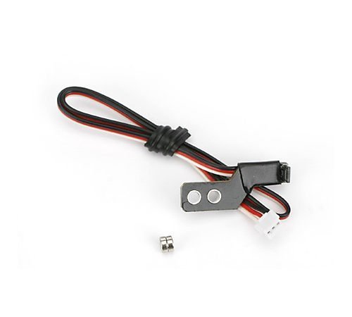
This sensor is HALL type which senses RPM by motion of the rotating magnets. Usually 1 - 2 neodymium magnets are mounted on the fan of combustion helicopters with a Nitro motor.
1 Required modification
For usage with the Spirit units a small modification of the sensor cable is needed.
- Check red and black wires in the connector - Align sensor has a unique colors.
- Crimp a new pin from the Servo connector.
- Wire layout
- White wire: RPM Output Signal
- Red wire: Ground
- Black wire: 3.3V - 8.4V
Only one pin is needed but unused pins can be inserted as well for increased safety.
For this operation you will need a new servo connector and optionally a crimping plier.
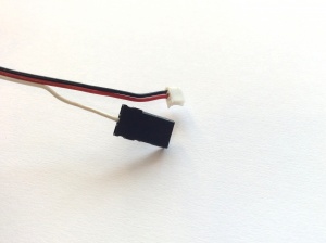
For users that do not use a Spektrum satellites it should look in the following way:
If you are using Spektrum satellites, then instead of the Spektrum connector you will need second servo connector which can be powered from the BEC port. Make sure that the Black wire is in the middle of the Servo connector.
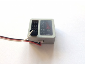
As the last operation, connect it to the unit. Please note Spirit 2 and Spirit RS has this connector upside down. Wiring is identical
2 Magnet mounting
We highly recommend to orientate each magnet as Active for a proper operation. More magnets will result in a higher reading resolution thus increased readout precision.
3 Governor Settings
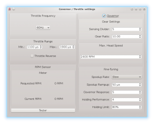
When sensor is connected, please set the Sensor Divider parameter so that the value will represent count of the active magnets. Usually it is 1 or 2 magnets.


