Câblage
Le Spirit peut être utilisé comme un gyroscope dédié à l'anticouple ou bien comme un système flybarless. Le câblage du module dépend du type de récepteur utilisé.
NOTE
Le Spirit est pré-programmé pour utiliser des servos avec un neutre à 1520µs et une fréquence de 50Hz. Veuillez vous assurer que les paramètres de servos sont conformes à ceux spécifiés par le fabriquant.
Si le neutre d'un de vos servos est différent, comme 760µs, ne le connectez pas maintenant parce qu'il pourrait être endommagé.
Certains connecteurs ont des dimensions non standard qui pourraient gêner les connecteur adjacents. Nous recommendons dans ce cas de remplacer ces connecteurs non standards par des connecteurs de type JR ou Futaba.
Ne branchez jamais un connecteur pour alimenter le module dans les positions SYS ou ELE/PIT/TAIL. Vous risquez d'endommager le module.
Contents
1 GYROSCOPE AUTONOME ET BARRE DE BELL
Les possesseurs d'hélicoptères à barre de Bell peuvent utiliser le gyroscope à conservateur de cap, qui garde la direction de l'anti-couple donnée par l'émetteur quelques soient les effets du vent ou de forces extérieures.
Connectez le servo d'anti-couple au port "CH4" du module Spirit. Si vous utilisez aussi un récepteur standard, vous aurez besoin de connecter la voie GEAR (ou AUX) de votre récepteur au port AUX du module Spirit. Vous devrez aussi connecter le port RUD de votre récepteur au port RUD du module Spirit.
Même si vous avez un hélicoptère à barre de Bell, vous pouvez connecter le module de la même manière qu'avec un hélicoptère flybarless. Cela permet d'utiliser tout le potentiel du module comme la Stabilisation et le mode Sauvetage. Pour que ceci fonctionne correctement, il est nécessaire ce cocher "Flybar mechanic" dans l'onglet Stabi durant la configuration. Tous les autres paramètre peuvent être ajustés de la même façon que sur une tête flybarless.
2 FLYBARLESS
Flybarless helicopters can take advantage of the full capabilities of the Spirit unit. The Spirit will stabilize the model on all axes and also make it less affected by wind, extend flight times and increase the agility of your model. When properly set up, flight characteristics should be more stable which will give you the confidence to carry out even the most challenging maneuvers.
Flybarless rotor blades are also different from blades designed for flybarred models. For optimum flight characteristics it is recommended to use them. When using the Spirit unit as a flybarless system, all servos should be connected in the corresponding positions:
| Spirit |
| CH1 – Pitch / Aileron servo |
| CH2 – Elevator servo |
| CH3 – Aileron / Pitch servo |
| CH4 – Rudder servo |
| Spirit Pro |
| CH1 – Pitch / Aileron servo |
| CH2 – Elevator servo |
| CH3 – Aileron / Pitch servo |
| CH4 – Rudder servo |
| CH0 – auxiliary (optional) cyclic servo for CCPM 90 swashplate type. |
NOTE
Servos at positions CH1 and CH3 are dependent on the Swashplate settings.
Aileron servo on the model is mostly positioned on the right side while pitch on the left side.
3 CONNECTION OF STANDARD RECEIVER (PWM)
Spirit – receiver type: PWM
Spirit Pro – receiver type: PWM
For standard receivers it is necessary to use two normal and one special cable. Three connectors from the special cable should be plugged into the receiver and the end of this cable to the unit.
The unit is powered by two cables from the receiver connected to AUX and RUD positions. The Throttle cable should be connected to the receiver as well.
The easiest way you can start connect RUD with Rudder output in the receiver. Then continue with AUX which should be connected to the Gyro Gain channel output. Next, connect the Aileron, Elevator and Pitch (Aileron 2) channels. If you are not sure whether you have the correct output or not, you can plug in one servo and power the unit to verify that your connection is correct. This can be repeated for each servo. The diagnostics tab is very helpful too.
Never plug a connector for powering the unit to SYS or ELE/PIT/AIL ports.
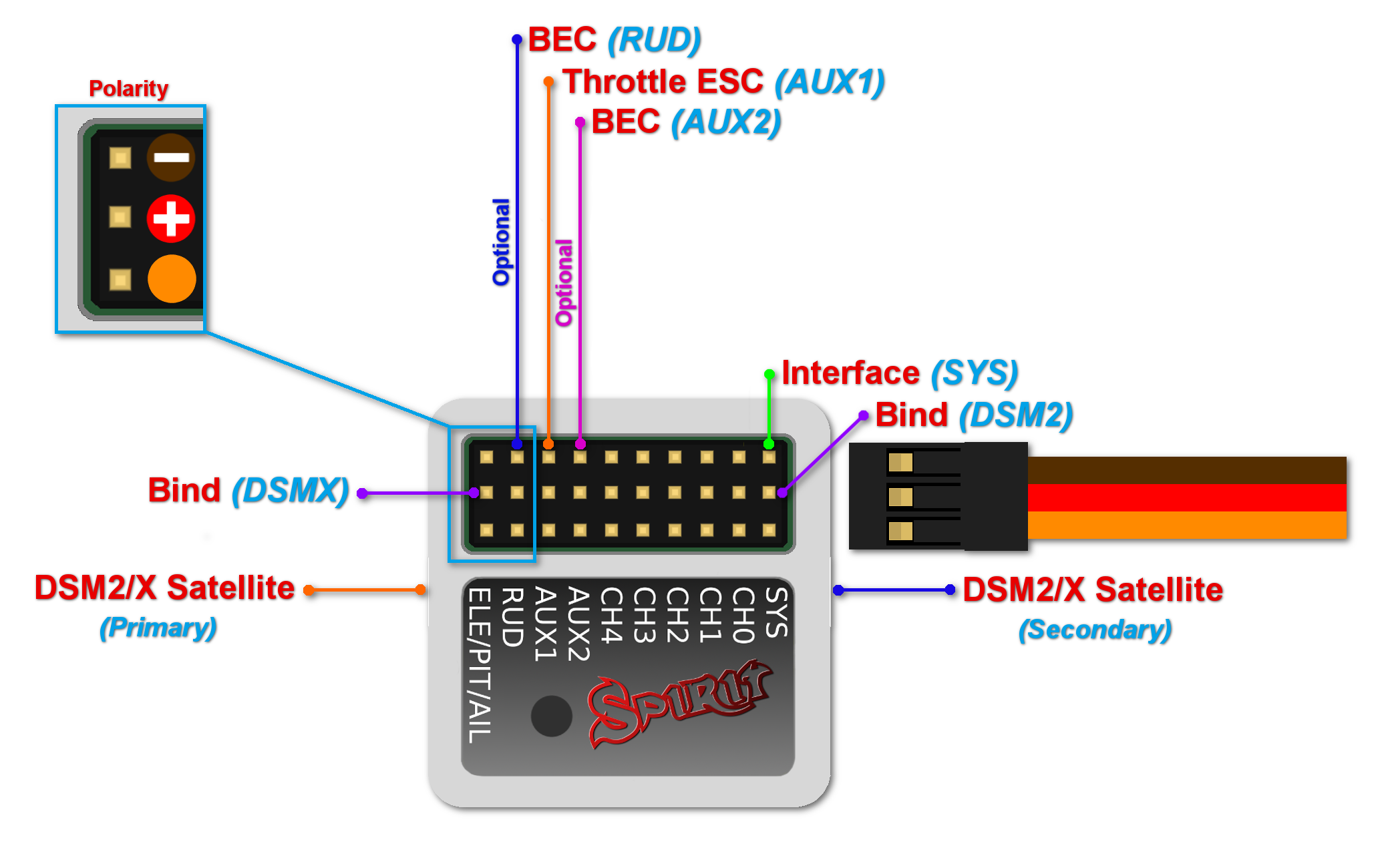
4 CONNECTION OF SPEKTRUM DSM2/X SATELLITE
Spirit – receiver type: Spektrum DSM2/X
Spirit Pro – receiver type: Spektrum DSM2/X
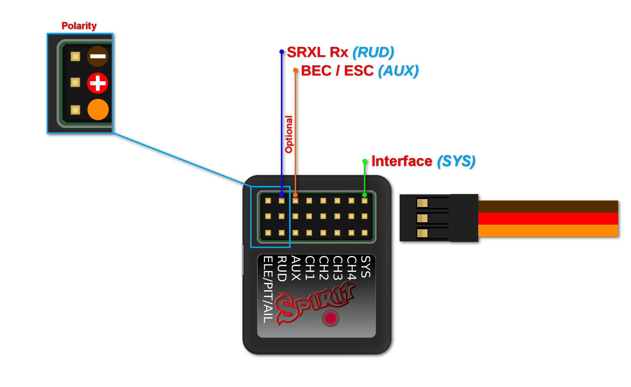
Connection to a BEC is optional. If the model is powered by an external BEC, this must be connected to the RUD port. Also the power lead from the ESCs internal BEC must be disconnected.
To bind the satellites, insert a bind plug in the SYS port for DSM2 satellites or the ELE/PIT/AIL port for DSMX satellites. Power cycling the Spirit start the bind process. Once successfully bound, the STATUS LED will go out and the satellite LED will come on.
If the second satellite fails to bind, swap the satellites and repeat the bind process.
Be sure Receiver type in the software is configured to Spektrum DSM2/X or else binding process will not work. Never plug a connector for powering the unit to SYS or ELE/PIT/AIL positions.
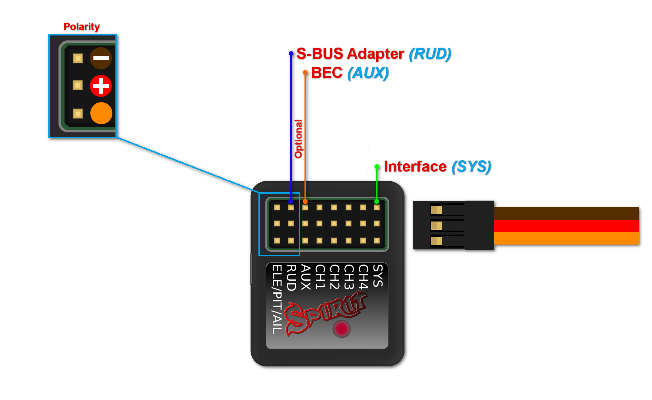
5 CONNECTION OF FUTABA S-BUS RECEIVER
Spirit – receiver type: Futaba S-BUS
Spirit Pro – receiver type: Futaba S-BUS
Connection to a BEC is optional. For models of 500 size and larger it is recommended to use dual power supply cables due to the increased power consumption. That means besides the S-BUS cable, an additional power supply cable should be connected to the AUX port.
When using this type of receiver you can connect the throttle cable directly to the receiver. Alternatively, you can assign the throttle channel in the software and use the AUX as throttle output from the unit.
Never plug a connector for powering the unit to SYS or ELE/PIT/AIL ports.
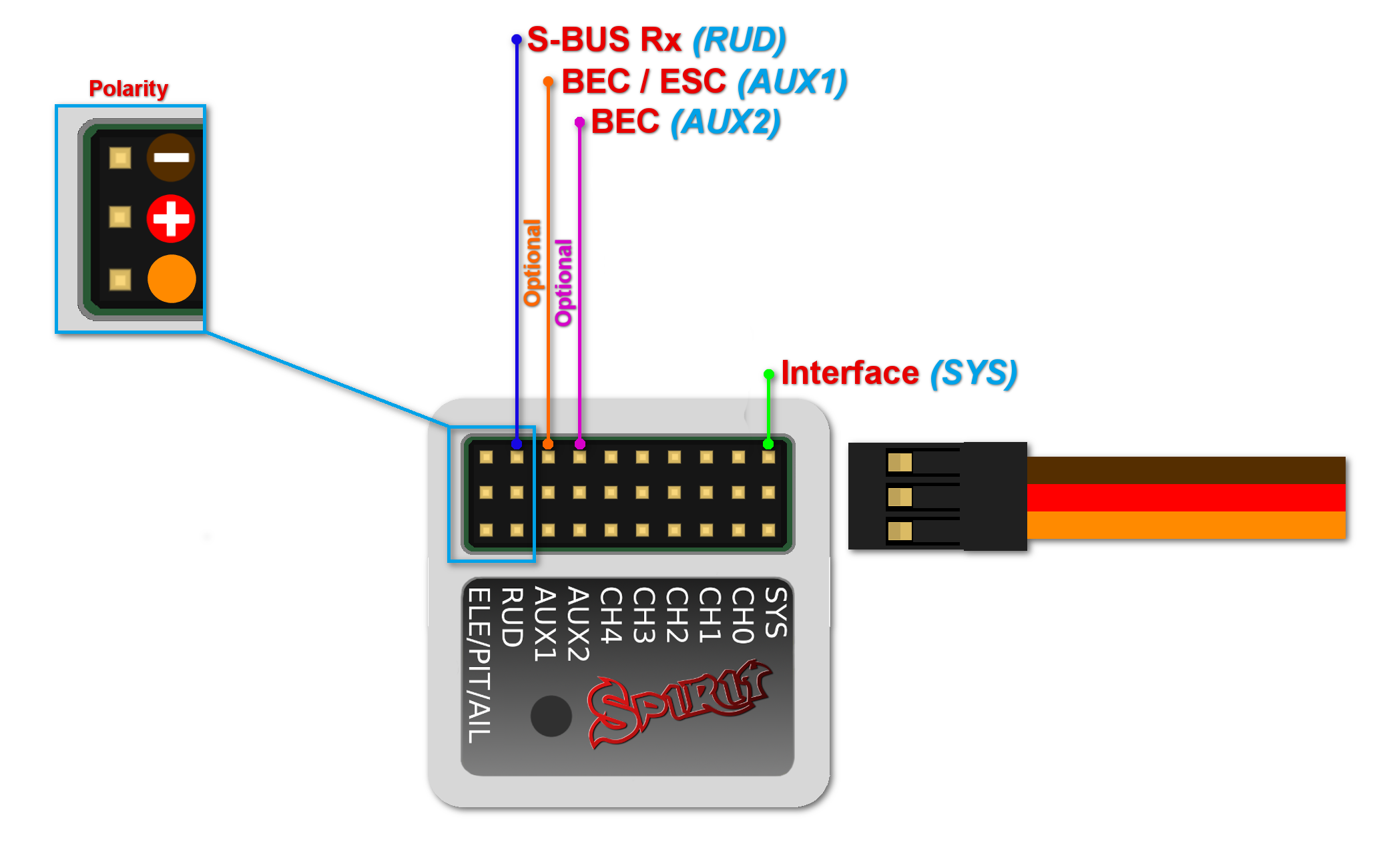
6 CONNECTION OF PPM RECEIVER
Spirit – receiver type: PPM
Spirit Pro – receiver type: PPM
NOTE
Connection to a BEC is optional. For models of 500 size and larger it is recommended to use dual power supply cables due to the increased power consumption. That means besides the communication cable, an additional power supply cable should be connected to the AUX port.
When using this type of receiver you can connect the throttle cable directly to the receiver. Alternatively, you can assign the throttle channel in the software and use the AUX as throttle output from the unit.
Never plug a connector for powering the unit to SYS or ELE/PIT/AIL ports.
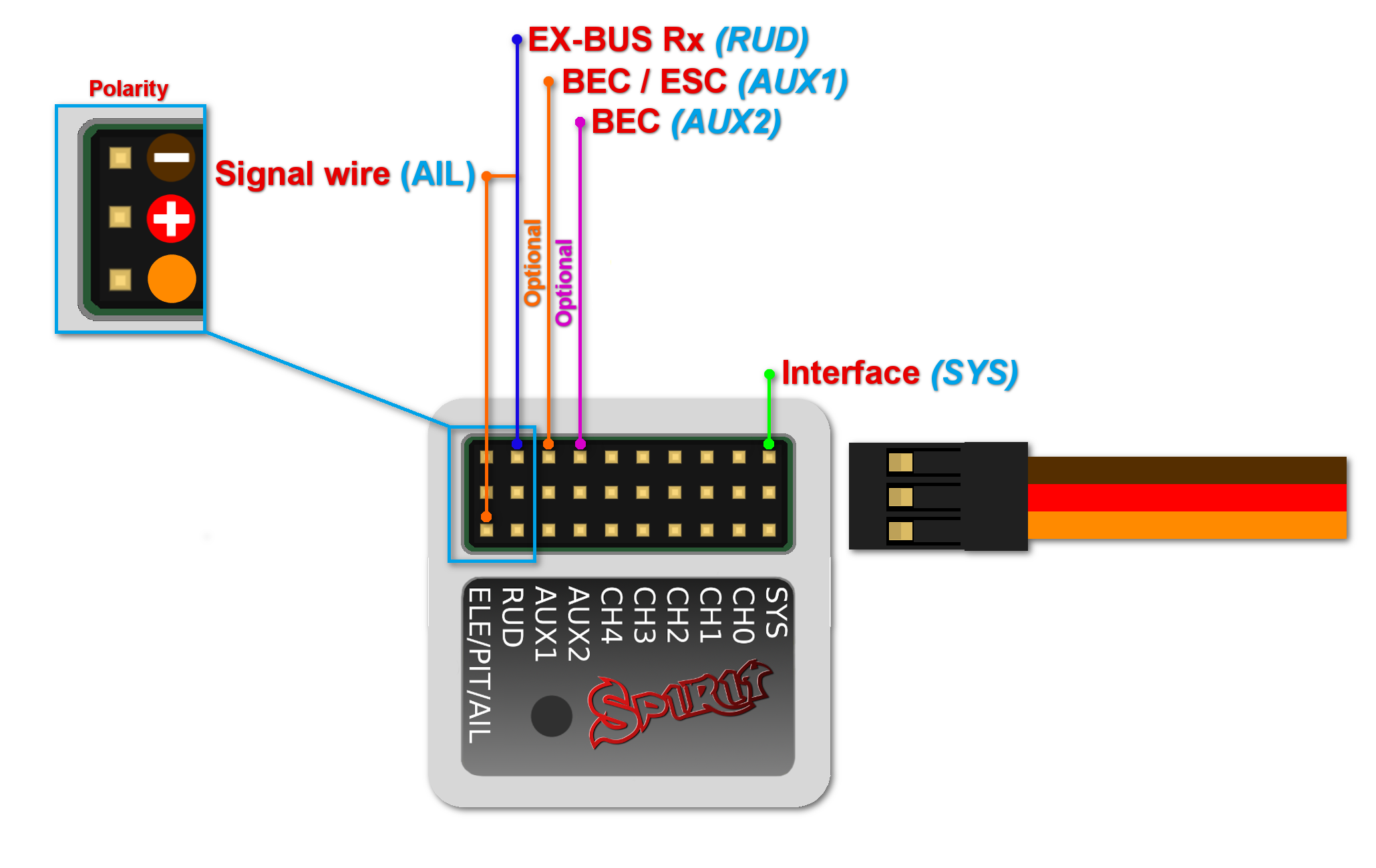
7 CONNECTION OF JETI EX BUS RECEIVER
Spirit – receiver type: Jeti EX Bus
Spirit Pro – receiver type: Jeti EX Bus
This connection type now supports the new integration with JETI Model transmitters. You can now fully configure the Spirit unit remotely through the JETI Model transmitter.
Remember to configure the receiver type through the software or the integration will not work. Also, it is necessary to download Spirit.bin file from the website. Move the file to the Devices directory in the SD card of your transmitter.
NOTE
Connection to a BEC is optional. For models of 500 size and larger it is recommended to use dual power supply cables due to the increased power consumption. That means besides the EX Bus cable, an additional power supply cable should be connected to the AUX port.
When using this type of receiver you can connect the throttle cable directly to the receiver. Alternatively, you can assign the throttle channel in the software and use the AUX as throttle output from the unit.
A special cable is needed to enable this communication.
Never plug a connector for powering the unit to SYS or ELE/PIT/AIL ports.
8 CONNECTION OF SRXL/SUMD RECEIVER
Spirit – receiver type: SRXL/SUMD
Spirit Pro – receiver type: SRXL/SUMD
NOTE
Connection to a BEC is optional. For models of 500 size and larger it is recommended to use dual power supply cables due to the increased power consumption. That means besides the communication cable, an additional power supply cable should be connected to the AUX port.
This protocol family can work with a wide range of receivers.
Thus you can use Multiplex SRXL, BeastX SRXL, Graupner SUMD, Jeti UDI, Spektrum SRXL and more.
When using this type of receiver you can connect the throttle cable directly to the receiver. Alternatively, you can assign the throttle channel in the software and use the AUX as throttle output from the unit.
Never plug a connector for powering the unit to SYS or ELE/PIT/AIL ports.
9 CONNECTOR ORIENTATION
All cables connected to the unit must be oriented so that the signal wire (Lightest color wire) is closer to the connector pin label, towards the center of the unit. This orients the negative (darkest color wire) toward the edge of the unit.


