Difference between revisions of "Configuration/ru"
(Created page with "Никогда не подключайте разъем с питанием в гнезда SYS или ELE / PIT / AIL.") |
(Created page with "Если устройство еще не настроено (например, новое), рекомендуется пока не подключать сервоприво...") |
||
| Line 41: | Line 41: | ||
'''Никогда не подключайте разъем с питанием в гнезда SYS или ELE / PIT / AIL.''' | '''Никогда не подключайте разъем с питанием в гнезда SYS или ELE / PIT / AIL.''' | ||
| − | {{Info|[[File:Info.png]] | + | {{Info|[[File:Info.png]] Если устройство еще не настроено (например, новое), рекомендуется пока не подключать сервоприводы. |
| − | + | ||
}} | }} | ||
Revision as of 12:47, 12 October 2018
Конфигурация - это следующий и один из самых важных шагов для правильной работы системы.Конфигурация выполняется с использованием программы настройки, которое сочетает в себе эффективность и простоту настройки параметров, в том числе расширенных.
Программное обеспечение включает Мастер установки. Настоятельно рекомендуется использовать Мастер, он проведет по всем этапам настройки, с самого начала и до первого полета.
Contents
1 ПОДКЛЮЧЕНИЕ К ПК
Перед началом фактической настройки необходимо подключить Spirit к компьютеру через USB-порт. В зависимости от операционной системы и компьютера, возможно, потребуется установить драйвер после подключения кабеля к порту USB.
Программа настройки Spirit доступна для следующих операционных систем:
- Microsoft Windows
- Apple OS X
- GNU/Linux
- FreeBSD
После подключения и установки драйвера, в диспетчере устройств должен появиться виртуальный COM-порт.
MICROSOFT WINDOWS
Установите драйвер через установщик программного обеспечения. Этот процесс будет описан в следующем разделе.
APPLE MAC OS X
Для правильной работы важно загрузить и установить драйвер со следующего URL:
OSX - 10.12
OSX - 10.13+
GNU/LINUX & FreeBSD
Ничего устанавливать не нужно
1.1 WIFI-LINK
Теперь программа настройки может подключаться к Spirit с помощью модуля Wifi. Он называется Spirit Wifi-Link. Wifi-Link может полностью заменить USB-интерфейс. Таким образом, пользователь может выполнить все настройки по беспроводной сети. Вы можете найти описание соединения на странице инструкции Wifi-Link.
2 СОЕДИНЕНИЕ С УСТРОЙСТВОМ
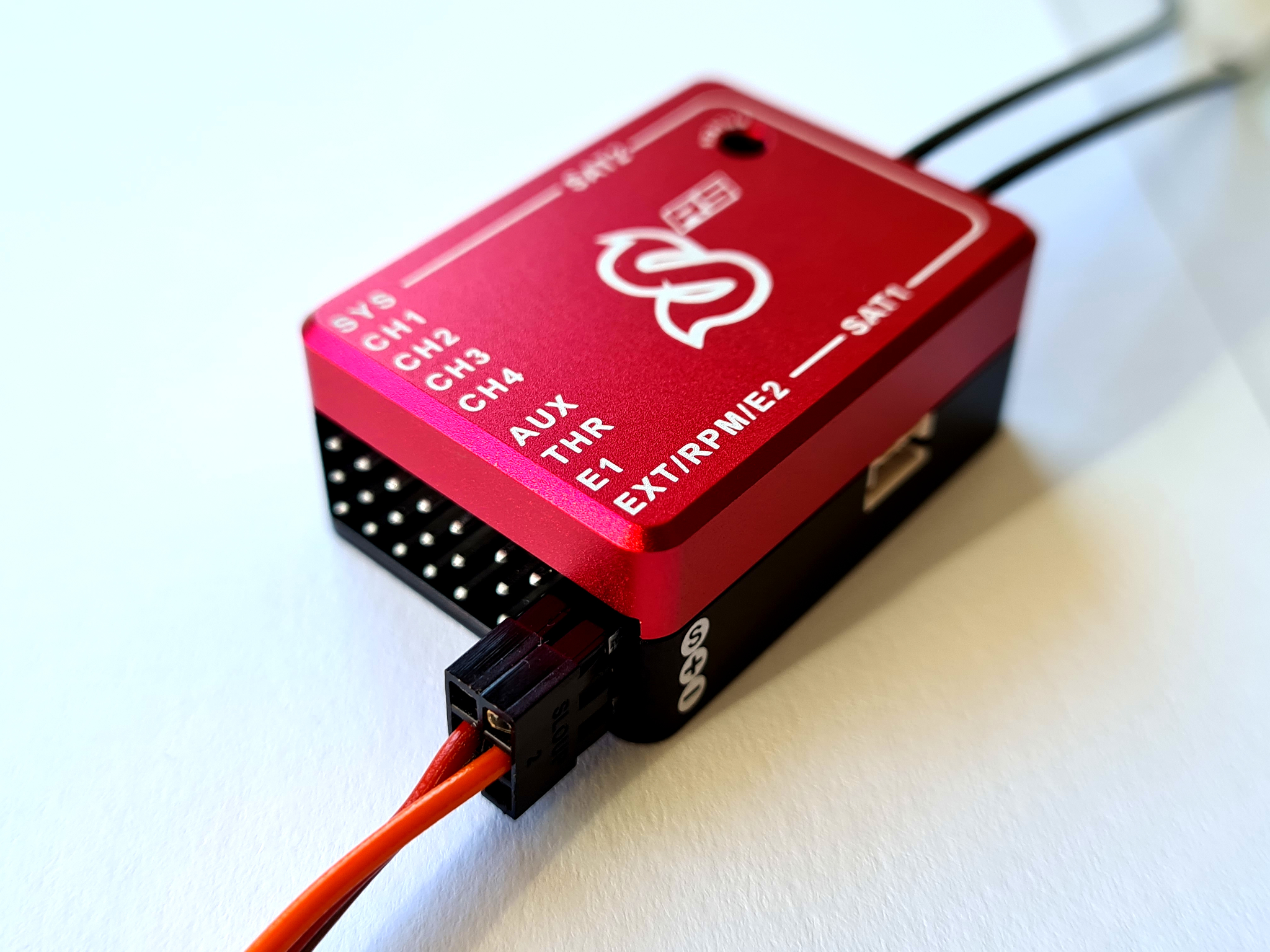
Если вы уже подключили USB-интерфейс к компьютеру, подключите интерфейсный кабель к порту SYS. Spirit не может получать питание от USB-кабеля / SYS-порта, поэтому необходимо подключить питание от приемника, BEC или бортового аккумулятора. Порты RUD и AUX можно использовать для подачи питания на Spirit FBL, напряжение 3 - 15 В. Средний провод должен быть плюсом питания.
Никогда не подключайте разъем с питанием в гнезда SYS или ELE / PIT / AIL.
Если устройство еще не настроено (например, новое), рекомендуется пока не подключать сервоприводы.
3 SOFTWARE INSTALLATION
Below are the installation instructions for the supported platforms. The configuration software is available on the Spirit System website: spirit-system.com.
MICROSOFT WINDOWS
Run the installer and follow the wizard.
If the driver is not installed yet, you will be given the option to do so during the
installation process.
The installer will go through all the necessary steps to prepare your computer
for running the configuration software. Upon completion of the installation
process, the configuration software can be launched from your desktop or
program list, called “Spirit Settings”.
For detailed guide for Spirit Settings installation, launching and troubleshooting open Spirit Settings under Windows page.
APPLE MAC OS X
Install the downloaded software by opening the DMG file and then moving the
content to your Applications folder. Configuration software can be launched from
the Applications folder with “Spirit-Settings“.
GNU/LINUX a FreeBSD
Extract all the files from the downloaded archive to, for example, your home
directory.
Configuration software can be launched from the newly created directory
with the file „settings.sh“.
Linux Mint (or compatible) installation guide is available at Spirit Settings under Linux page.
4 SOFTWARE STARTUP
Once the software is installed, ensure your Spirit unit is connected via USB to the SYS port, powered on and initialized (LED lights are on), then run the software on your computer.
Start the Spirit Settings from your desktop or a directory where it was installed.
The configuration software should be started after the unit has initialized. Whenever the Spirit FBL is initialized (status LED is on) and connected, you can make adjustments to the settings. Configuration during flight is not possible due to the associated safety risks.
PROBLEMS ON WINDOWS
If the configuration software is unable to detect a valid COM port, you can try
starting the software as Administrator.
Alternatively, check the COM port number. If the value is too high try
reconfiguring the port number (Silabs device) to, for example, COM1 – COM4.
For notebooks it is also worth disabling any USB power saving features in Device
manager.
PROBLEMS ON MAC
If the configuration software is unable to detect the USB interface, make sure that the Driver is installed.
It is very important that the version is correct else it can lead to an instability.
5 SOFTWARE USAGE
After successful connection of the Spirit FBL unit, all configuration features should be accessible. If not, try to either choose another COM port (Device) or try to restart the software, disconnecting the unit from the power supply and repeating the procedure.
Make sure the software is launched after the unit has initialized.
5.1 CONNECTION TAB
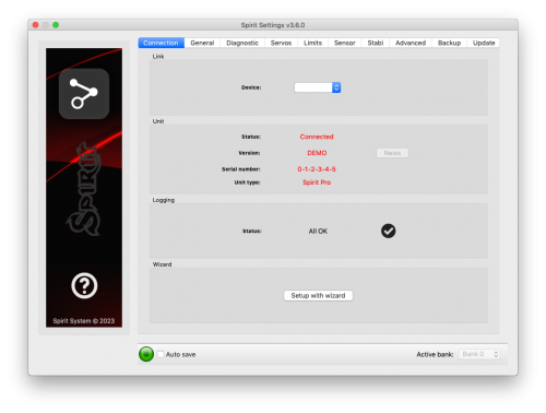
This tab indicates the current status of the connection, informs you about the current version of the firmware, displays the serial number of the connected unit and allows you to change the COM port. In addition it features a wizard for initial setup.
We recommend using this wizard, as it will guide you through a basic setup in the easiest and simplest way.
5.2 GENERAL
If you have already set up the unit using the wizard, you can make additional adjustments to your setup here. All values relate to the settings you selected in the wizard.
Whenever parameters are changed, the new value is immediately applied but not saved. Unless settings are manually saved, after disconnecting the power supply all unsaved changes will be lost. (see Backup tab.)
Position
Selects the position in which the unit is attached to the model.
(See section 3 - Installation)
Swashplate
Select the swash type of your model.
In most cases it is CCPM 120° or CCPM 120° (reversed).
Any swash mixing in the transmitter must be turned off. It must be configured to H1 (single servo) type.
Receiver
Select the type of receiver you are using:
- PWM – standard receiver.
- PPM – single line connection.
- Spektrum DSM2/DSMX – DSM2 or DSMX satellite. (for Spektrum integration).
- Futaba S-BUS – receiver connected via SBUS. (for Futaba telemetry)
- Jeti EX Bus – receiver connected via EX Bus (for JETI model integration).
- SRXL/SUMD – receiver connected via SRXL, SUMD, UDI (for HoTT integration).
Flight style
Sets how the model will behave in flight.
This parameter is used to control and adapt flight behavior according to the
requirements of the pilot. It has significant impact on a pirouetting maneuvers (cyclic steering), but not pirouettes (rudder) itself.
Parameter has no impact on a stability. Generally, for bigger models higher value is recommended.
Lower values mean that the model will behave in a more consistent, controlled manner and will feel more linear and robotic. It could introduce a delay to the steering. Angular momentum will be held more constantly.
Higher values mean a more natural behavior. The response to stick movements will be more flybar-like where fast movement will introduce agressive response. But a small movements near the center will be more precise. It can help to make tic-tocs faster. End of each cyclic input will become faster.
Recommended value for the most pilots: 4.
Channels
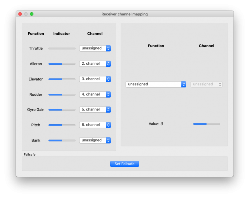
After clicking the button, the window with channel assignment is displayed.
You can assign any channel to any function here. The number of available
channels is dependent on the receiver type. Remember to only assign one
channel to each function.
When a channel for Throttle function is assigned, throttle output from the unit
can be obtained from the AUX position.
When a channel for Bank function is assigned, then Bank switching is activated
(See chapter 5.6).
When a channel for Gyro Gain function is unassigned, it is possible to configure
gyro gain directly through this software in Sensor tab. The unassigned channel
could be used in another way, e.g. for Bank switching.
Failsafe
For a PPM, Futaba S-BUS, Spektrum DSM2/X, Jeti EX Bus, SRXL/SUMD receiver types you
can set the Failsafe directly in the unit. Channel values are stored
immediately after clicking the Set failsafe button. In case that the signal is
lost for more than 1 second it will set the values automatically in the flight.
With other receiver types the Failsafe is programmed in the transmitter or receiver.
Realtime tuning
By assignment of a parameter (P) it is possible to change the settings directly from your transmitter.
You can comfortable set selected parameter by changing channel value (for example by a potentiometer).
Thus you do not need a configuration software at all. Usual transmitter is enough.
A change in corresponding channel will immediately change value of the parameter. Maximal deflection will set the highest value of the parameter, while the minimal deflection will set the lowest value.
Realtime parameter tuning has the highest priority. So when enabled, saved value from the profile or a Bank will be ignored.
This functionality is enabled only when the configuration software is not connected. This will prevent from a possible collisions. As soon as the software is disconnected, selected parameter is configured by the channel value. In case that the software is started again, it will keep value from realtime tuning in it's memory. However, with opened software policy described above will be applied again (Realtime tuning is inactive and value will be intact even if channel is changed).
You can configure 3 different parameters and functions simultaneously with this feature.
If function (F) is assigned, it is engaged when it's value is equal to 1. Vibration analysis function allows you to measure vibrations during the flight. It is described later in the Diagnostic tab section.
When parameter tuning is complete, it is recommended to open the software and save the settings to the unit. Then unassign the parameter so the value can't be changed anymore.
It is recommended to always carry extreme caution to not loose control of the model!
5.3 DIAGNOSTIC TAB
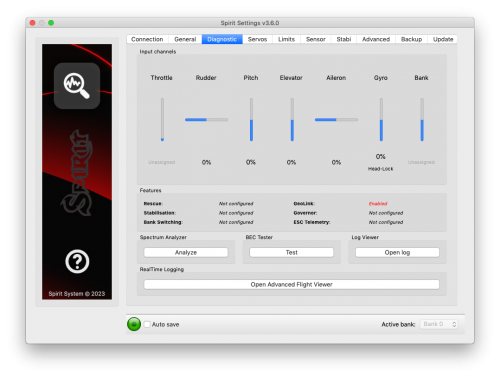
Once the settings in the previous tab have been completed, it is now recommended to make any adjustments and changes required in the transmitter so that the transmitter controls match the displayed system's outputs. Generally, each transmitter is different and the center of the channel is never exactly the same. Wear and environmental influences can also have an effect causing the center of the channels to fluctuate. Another consideration is the maximum and minimum value of each channel. Here, you adjust your throws using your transmitter's servo endpoint adjustments.
For a proper operation of the unit, it is necessary that movement of each channel correspond with the bars. Direction of the movement must match with the sticks as well.
Secondly, it is necessary to check the values of aileron, elevator, pitch and rudder channels. These channels must be centered at approximately 0%. The unit automatically detects the neutral position during each initialization. Do not use subtrim or trim functions on your transmitter for these channels, as the Spirit FBL unit will consider these as an input command.
Ensure all subtrims and trims are zeroed.
It is also recommended to set the maximum and minimum values. Test the minimum and maximum throws for all channels, if these values are not equal to -100% and 100% in the diagnostic tab it is necessary to adjust your transmitter endpoints to correct this.
After these adjustments, everything should be configured with regards to the transmitter. If some channels oscillate around the center, it may mean wear of the transmitter potentiometers. This can be compensated for by increasing stick deadband in the Advanced tab. (Covered later)
If the values in the aileron, elevator, or rudder channels are shown in bold, the system is recognizing a command to move/rotate the axes.
To determine Gyro Gain and Mode of the rudder gyro you can check Gyro bar.
SPECTRUM ANALYSER
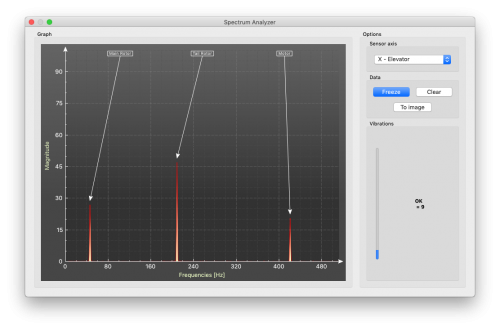
The Spectrum analyser is a tool for measuring the amount of vibrations on your model. It is a diagnostic tool designed to determine which rotating part is causing a problem. With this information you can easily identify and fix any problems with your model.
To check condition of the model you can see "Vibrations" bar. This indicate general vibration amplitude in selected axis.
It is possible to measure vibrations in three separate axes:
- X - elevator axis
- Y - aileron axis
- Z - rudder axis
- In-Flight - flight vibration player
The live graph shows frequencies for the currently selected axis. This enables you to see both the frequency and magnitude of the vibration on the selected axis.
Vibrations are transmitted to each axes dependent on several, various factors. Frequencies and magnitude are dependent on the model construction. Generally, the vibrations are the highest on Y axis (aileron) but we recommend you check all axes each time you are doing measurement. However vibrations should not exceed 50% for all axes at any time. In the case vibrations are at 90% or more, the model has an issue that needs to be rectified. Should the magnitude exceed 90% on any of the given axes, it is recommended to fix whatever issue is causing these extreme vibrations before flying the model. Even though Spirit FBL unit is highly resistant to vibrations, these could cause unwanted interactions with the Spirit FBL unit and could also cause mechanical failure of the model. Such high vibrations can cause Loctite to fail and other mechanical parts to break.
Vibration levels:
- Vibrations up to 50% - vibrations at a normal and acceptable level
- Vibrations between 50% and 90% - raised vibration levels
- Vibrations exceeding 90% - extreme vibration levels
As well as overall vibration levels not exceeding 50%, any specific frequency (peak) should not exceed 50%. Anything above this level should be cause for concern and requires further investigation.
For comparing the graphs, you can use the Freeze button. The current live graph is displayed and the graph captured using the Freeze button is saved and will be displayed as subgraph. This graph can be deleted with the Clear button.
It is possible to save the Spectrum analyser graphs. Using the To image button, the current graph will be saved as an image.
The Spectrum analyser is able to detect the vibration frequencies up to 500Hz (rotating parts at speeds up to 30,000 RPM).
Measurement procedure
- Remove main and tail blades from the model.
- Place the model on a suitable, soft surface (e.g. carpet, grass).
- Set blade pitch at approximately 0° on both main and tail rotors.
- Run the Spectrum analyser (this also freezes all servos).
- Spin up the motor to the usual flight RPM.
- Switch between the X, Y and Z axes, saving an image of each.
- Check vibrations in all axes.
- Stop the motor.
Recognizing vibrations
To recognize which component or part is causing abnormal vibrations it is necessary to determine the speed of the highest peaks. The main rotor will have the lowest speed and the tail rotor speed will be approximately 4.5x higher. Generally, the smaller the size of the model, the higher the headspeed will be.
In order to find out which part of the model is causing the unwanted vibrations, move cursor to the peak and check the head speed (RPM). The speed of the main rotor is usually in the range of 1500 to 3500 RPM. Therefore, if the speed is within this range, it is likely that there is a problem with the main gear, main shaft, main shaft bearings or rotor head itself.
Most excessive vibrations are usually, although not always, tail related. To check if there are vibrations coming from the tail you should find the frequency peak that is approximately 4.5x higher than the frequency of the main rotor.
Once you identify which part of the helicopter is causing the unwanted vibrations, you can gradually remove components of the suspect assembly, repeating the measurement process until the vibration disappears. Once the vibration levels have dropped to an acceptable level, you have found the suspect component and can replace it.
Measuring with tail blades installed carries some safety concerns and will also show increased levels of vibration.
Gasser motors shouldn't be operated without load! Vibration measurement can't be performed without blades.
In-Flight - vibration analysis from flight
This feature allows you to record vibration spectrum from any moment of the flight. By selected channel you can tell the unit when the spectrum should be taken. The spectrum can be later viewer in the Spirit Settings software with the In-Flight option in the Diagnostic/Spectrum analyzer. Saved vibration spectrum will be stored until unit will lost the power. Saved record is rewritten on repeated activation.
For vibration measurement in the flight set the Special function in the General/Channels. Assign function F: Vibration analysis with axis you want to measure. Then select a channel which will be used for activation of the function.
As soon as the value is equal to 1 the vibration spectrum is saved. The record is saved exactly at the moment when function will change it's state from 0 to 1.
During flight it is enough to change state of selected switch of your transmitter (for example 2-state switch). After landing you can connect unit with the software and open the Vibration analyzer (select In-Flight axis to display the spectrum).
BEC TESTER
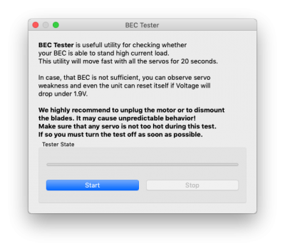
The tester is used for determining whether your power supply for the unit, receiver and servos is sufficient. The purpose is to achieve the biggest current spike and verify that your supply voltage will not drop under the safe level.
Click the Start button to start the test. After 20 seconds it should be finished.
If you will observe any issue, then your power supply is insufficient and should not be used. In this case power supply with higher current rating should used.
LOG VIEWER
The log is used to record events during flight. If a problem occurs and the reason isn't immediately known or evident, checking the log can help in identifying the issue.
It works in such a way that it records various events from the time the unit is powered on. If an event occurred you can see this in the log, reporting to the log is done every 10sec. When you click the Open log button you can see the current flight log which contains all the events from the last flight. When the power is disconnected, the log is cleared.
In the case of a major problem occurring during the flight ![]() , the log is then saved permanently to the unit's memory and remains there until such time as the log is opened.
If there is a saved log in memory, the user is advised with the message “Log from previous flight is available!” and the log from the flight when the problem occurred is opened. For example, when a signal is lost or the power supply failed you can find this in the log. The log from the first flight where the major problem occurred is always saved. If this is not opened, then it will not be overwritten with a newer one. In this state, the user is also notified by different cyclic pitch pump during the initialization process - elevator servo will change it's movement direction.
, the log is then saved permanently to the unit's memory and remains there until such time as the log is opened.
If there is a saved log in memory, the user is advised with the message “Log from previous flight is available!” and the log from the flight when the problem occurred is opened. For example, when a signal is lost or the power supply failed you can find this in the log. The log from the first flight where the major problem occurred is always saved. If this is not opened, then it will not be overwritten with a newer one. In this state, the user is also notified by different cyclic pitch pump during the initialization process - elevator servo will change it's movement direction.
The log can contain the following events:
- The model is in good condition. The unit did not recognize any problems.
-
- Sensor calibration was successful.
-
- Governor achieved requested RPM and is active from this moment.
-
- Cyclic achieved its maximum tilt angle. This indicates the model was unable to do the desired correction as necessary. In most cases it is not relevant. But it is possible that the value of the Cyclic Ring parameter is too low and the model can't rotate as fast as intended in the aileron/elevator axes. Alternatively, a too high value for rotational speed could be configured. It is also possible that in fast forward flight the model can pitch-up rapidly. We recommend to set this parameter as high as mechanically possible.
-
- The rudder servo reached its configured limit. When this event occurs before or after a flight it is not a problem. If you see this during flight it indicates that the rudder did not operate correctly. In most cases it is visible during flight as poor rudder response or “blow out”. If the model is set up correctly then it could be due to low rudder efficiency such as the tail blades being too short or headspeed too low. There is also the possibility of a mechanical issue or with the rudder limits being inadequate.
-
![]() RPM Sensor data are too noisy:
RPM Sensor data are too noisy:
- RPM readout is very unstable and are oscilating more than +/- 100 RPM. Data from the sensor are unusable for the Governor. Use additional shielding and mount a ferite rings. Increase value of the RPM Sensor filter parameter in the Expert settings.
-
- Received frame is unusable and will be ignored. In the most cases it does not present any problem. If the event is occuring often, then connection between receiver can be wrong or there is excess noise. Verify quality of the link and check the cable between unit and receiver.
-
- Sensor data reading failed - RPM sensor malfunction probably occured. Sensor is not sending data for 2 seconds or longer. Make sure, that the sensor wiring is correct and that the motor is spinning when Hold is disarmed.
-
- Signal lost suddenly. This problem should not occur at any time and must be resolved before the next flight. There could be a problem with the receiver and/or transmitter antennas. It could be a faulty receiver cable or the connection between the unit and receiver. In some cases signal loss can happen because of electrostatic discharge caused by static build up, this usually occurs in belt driven helicopters.
-
- The main loop was delayed. This can happen when wiring is incorrect or there is abnormal electrical noise interference with the unit, for example, from a BEC. If using the configuration software it could mean the link to the Spirit FBL unit is slower than it should be.
-
- Power supply voltage is lower than 2.9V. This mean you have to use a BEC that is capable of handling higher loads. In rare cases it could be faulty connections in cables.
-
- Vibration level achieved the level that is not normal and can affect integrity of the helicopter. During hard 3D maneuvers the event can occur more frequently.
-
All reviewed logs are saved as PDF files into Documents directory.
5.4 SERVOS TAB
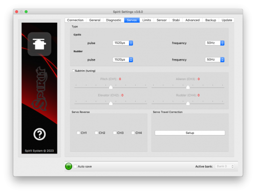
This tab is used for servo configuration, care should be taken to ensure correct frequencies are used and that the directions are set correctly.
Type
In this section, set the values for neutral pulse and frequency according to your servo manufacturer specifications.
For analog servos the frequency is usually a maximum of 60Hz.
Subtrim (tuning)
Ideally, without the rotor head installed, use a swash leveler to align the swash and servo horns so that the swashplate and servo horns are horizontal and perpendicular to the main shaft.
This is done by ticking the item Subtrim (tuning). This will put the Spirit FBL unit into a special mode where the collective position will be neutral with the servos centered. In addition, stabilization will be disabled.
Servos can easily be adjusted at this time. When completed, the swashplate should be exactly perpendicular to the main shaft and in addition collective pitch should be at 0° (it is possible to measure the pitch angle using a pitch gauge with rotor head and blades attached).
In most cases, it is also necessary for servo horns to be perpendicular to the main shaft. All servos, i.e., CH1, CH2, CH3 and CH4, are set separately on individual sliders. CH1 and CH3 are the aileron servos. CH2 controls the elevator and CH4 controls the rudder.
It is also necessary to set the subtrim and mechanics of the rudder so that the servo horn is perpendicular to its case and rudder pitch is at 0°. This setting will affect rudder stop performance.
Once set up, un-tick the Subtrim (tuning) check box to turn off this special mode.
After exiting the special mode, stabilization and rudder will work again. Be sure your collective pitch channel is configured correctly in the transmitter. That means you should see -100% to 100% in the diagnostic tab. Double check that 0% in diagnostic tab corresponds with middle position of your collective/throttle stick (with linear -100% - 100% collective pitch curve).
Micro helicopters and µSpirit: When Tail rotor is driven by a dedicated motor, the Rudder ESC performance can be noticeably improved by configuring Low RPM value to achieve the lowest spinning RPM for the Tail rotor. This can be configured by Subtrim (CH4) - Low RPM - the value has impact on lift off and symmetrical turning performace.
Servo reverse
This allows you to choose which servos should have their direction of motion reversed. While changing the collective pitch all servos should move in same direction. After this settings the model should react correctly to the sticks movement.
This parameter is the most important!
Servo travel correction
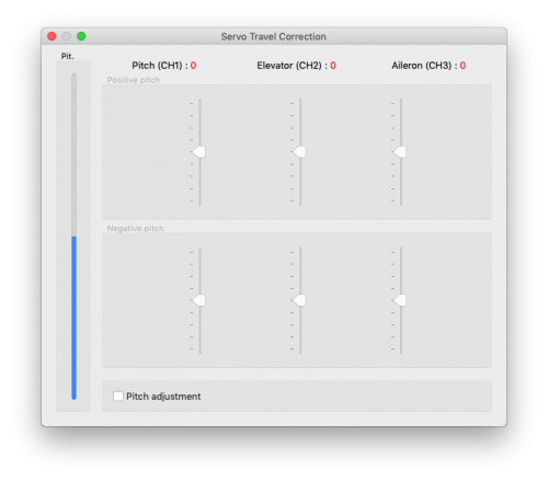
Here, you are able to modify and correct travel for each servo individually. Some servos are not very accurate in regards to travel at their limits and this inaccuracy may have a negative impact on flight characteristics. Once in this section of the software, the unit switches to a mode for doing these corrections.
It is expected that in the previous step, Subtrim (tuning), the swashplate was set at zero collective (0° rotor blades pitch). The procedure is such that you should use a swash leveler to determine whether there is any deviation on any of the servos in the lowest and highest points of collective throw. For both positive and negative positions, it is necessary to set the values separately – this is the reason for 6 sliders. If the travel is less than required, increase the value. If too much, decrease. To activate sliders in the secondary part move your collective to opposite direction.
This correction is also useful if there is asymmetric geometry on the helicopter causing issues such as the inability to achieve equal positive and negative pitch values. In this case, it is necessary to modify the positive or negative sliders for all three servos. If you are unsure about your settings, it is better to leave the sliders in the Middle. (position 0)
5.5 LIMITS TAB
This tab affects limits and servo travel ranges.
Cyclic Ring (tuning)
This parameter sets the electronic cyclic ring, which allows the model to achieve the largest cyclic ranges without mechanical binding (binding of servo horns, pushrods and linkages).
The settings here should be done very carefully to avoid damage to the model or it's associated electronics. Never exceed recommended angles by manufacturer of the model, otherwise a boomstrike can occur.
First, set your desired Collective range, for example, +/-12°. We recommend
using a -100% to 100% linear collective pitch curve in the transmitter.
Now it is time to set the Aileron/Elevator maximum cyclic pitch range.
Try to set the largest possible deflection. Generally the Cyclic pitch angles (range) should be equal or lower than Collective pitch.
This parameter does not directly affect the speed of rotation, but if it is too low, the model may not have consistent pitch and roll rates.
The setting should be done with 0° collective pitch. Then carefully move with sticks in all directions to ensure that mechanical binding
does not occur. This should also be done for the maximum and minimum Collective pitch.
If you increase the collective pitch range, this parameter must then be
checked and in some cases adjusted to ensure no binding occurs at your new
maximum and minimum pitch ranges.
If the selected cyclic ring range is insufficient, it is possible that pitch-up can happen during fast forward flight (even if the pitch-up compensation is at its maximum value). This is because the model will not be able to add sufficient corrections with the configured range.
Rudder end-points (tuning)
Left / Right limit - Sets the minimum and maximum deflection of rudder rotor blades.
We recommend setting these values for both directions to the maximum
allowed range by the manufacturer of the helicopter. Otherwise, the rudder
may not be able to keep the yaw direction during demanding maneuvers and
tail blow outs may occur.
Do not exceed allowed limit for your model.
Micro helicopters and µSpirit: When Tail rotor is driven by a dedicated motor, the Rudder ESC must be connected at the CH4 port. Rudder end-points are then used to set available Throttle range for the Rudder ESC from 0% (Stop) to 100% (Full). We recommend to set Stop limit to 126 and Full limit to 150 for the beginning.
5.6 SENSOR TAB
This tab is the last important part of the settings which must be configured.
Sensitivity
The rotary dial adjusts the gyro sensitivity for aileron, elevator and rudder axes.
Cyclic gain – The higher the value is, the higher the accuracy within the control loop. The default value is preconfigured to 55% gain, for most models an optimal value of around 60% is suggested.
Rudder Common Gain – 1.00x means no multiplication. This is the recommended value for 550-class helicopters and smaller. For bigger helicopters it is often higher. 1.3x could be fine. Gyro Gain in your transmitter should be configured to approximately 50% for the first flight.
Rudder Gain – This parameter is enabled only in case of unassigned Gyro Gain channel. It replaces function of Gyro Gain from the transmitter, so you can directly set the value in the software.
Rudder Gain in the software or in your transmitter can be programmed in this way:
- Head-Lock mode: 1% to 100%
- Normal (Rate) or a special function: -100% to 0%
Negative gyro gain can be used to activate the rescue or the stabilisation modes – check the Stabi tab.
Some transmitters have a gyro range of 0 to 100% where 50% is the middle - zero gain (e.g. Spektrum DX6i). Others use a range of -100% and 100%, where 0% is the middle.
Rotation speed
The default value is 8 and will favor beginners more, the higher the value, the faster the rate of rotation. This factor also depends on the mechanical linkage ratio or D/R (Dual Rate) in the transmitter and also on the Aileron/Elevator limit.
Make sure the value is not too high else it can cause unwanted and inprecise movements.
default value - 8
We recommend to set the Cyclic rotation rate within a range of 8 - 11. Remember that DFC rotor heads tend to rotate faster so it's better to initially start with a lower value for them.
For the Rudder rotation rate pilots are preferring a range of 9 – 11.
5.7 STABI TAB
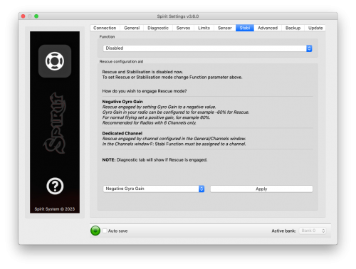
The Spirit unit offers you the options of model stabilization and rescue mode.The stabilization function, once activated, will recover the model to a horizontal position without any other input from the pilot, this can be used as a “bail-out” feature when trying new maneuvers and can help with the learning process.
Rescue mode complements the normal operation of the Spirit unit. If activated, the model will recover to a horizontal position and add collective pitch as per the settings. This function can be used any time when the pilot loses orientation or control of the model.
How to setup the Rescue or Stabilisation is described in the Stabi mode page.
From version 2.3.0 you can activate selected Function by two different methods:
- Negative Gyro Gain
- Separate Channel (NEW)
Negative Gyro Gain method is suitable for radios with low channel count (6 - 7). When you have available unused channel, method with a Separate channel is better and easier.
Currently selected mode is displayed in the Diagnostic tab.
Function
Here is where you select which mode should be activated at negative gyro gains.
- Disabled - Normal (Rate) gyro mode.
- Rescue (Normal) - Recovers the model to an upright horizontal position – skids always to the ground. This recovery mode is great for the beginners.
- Rescue (Acro) - Recovers the model to a horizontal position, inverted or upright, whichever is closer at the time of activation. For intermediatte and advanced pilots that are flying acrobatic manouvers.
- Stabilization (Normal) - stabilization mode - skids always to the ground. This mode is good for learning the basics such as hovering and slow transitions. Model is always pushed to the horizontal position.
- Stabilization (Acro) - stabilization mode - inverted or upright, whichever is closer at the time of activation. This mode is used for learning the basics of acrobatic maneuvers. If the sticks are in the center, the model has tendency for returning to the horizontal position.
- Stabilization (Scale) - stabilization mode - skids always to the ground. This mode is used for a scale flying. Gyro mode is Normal (Rate).
- Coaxial - stabilization mode - inverted or upright, whichever is closer at the time of activation. The steering behavior is very similar to a coaxial helicopters. Great for learning a hovering practices.
If using these modes, be sure your helicopter is initialized on a flat surface, not tilted to any side. Do not tilt the helicopter for more than 5 seconds.
The rescue mode is very demanding on the BEC. Be sure your BEC can handle such peak loads. In case it is is not sufficient your model could crash! Never exceed angles recommended by manufacturer of the model, else the mechanics can be damaged during the flight!
Flybar mechanic
If your helicopter is equipped with traditional flybar mechanics, you have to enable this parameter in order to use the stabilization or rescue modes. All settings are the same for flybarred helicopters except this parameter.
Flybarless helicopters must be configured and operated with the Flybar mechanic parameter disabled!
Rescue collective pitch
This determines how fast the model will ascend during the rescue mode.
100% means the maximum deflection of the blades, which was configured in the Servos tab.
It is very important to check whether the rescue mode works correctly before the first flight (on the bench without the motor/rotors running).
Collective pitch should be always positive with the rescue engaged - while helicopter is on the ground
Sticks priority
Specifies the amount of control while configured mode is activated.
The higher the value, the more the model will react to stick movements.
Direction control rate
This specifies the rate of controlling direction for the stabilization mode.
Low values are well suited for beginners to get coaxial like behavior. Higher values are more appropriate for scale flying.
Acro Delay
Specifies a time period for the Rescue (Normal), when the model is recovered from the inverted flight. Until the period is reached, the rescue has the same behavior as the Rescue (Acro). In this way, faster ascending to a safe level can be achieved.
5.8 ADVANCED TAB
This tab is for more advanced configuration of the Spirit FBL unit. It is recommended that you fully understand these parameters before adjusting them. However, it is essential to set geometry. Other parameters, however, depend on the preferences of the pilot.
Geometry 6° (tuning)
For proper operation of the Spirit unit, it is necessary to set this parameter correctly. Here, the unit is switched to a special mode for settings 6° of cyclic pitch on the main blades. It is necessary to set the value so that the blades angle is at 6° in the aileron axis. You need to rotate your rotor head with blades to be parallel to the longitudinal axis of the model. A higher value increases the angle; a lower one decreases the angle. Optimal head geometry should be in the range of about 90 – 160. If not in this range, it is recommended to adjust the distance of a ball link on the servo horns or perform other mechanical adjustments.
Collective Direction
Parameter to determine direction of the collective pitch.
In case of a Trailing Edge rotor head or if a mixing arms are present on the rotor head, tick the Reversed option. In the most cases the parameter is unticked.
Correct configuration is very important, else the collective pitch will be reversed.
Elevator filter
This parameter compensates elevator bouncing during aggressive maneuvers. The larger the value, more compensation is involved.
If this value is too high it can lead to a soft feeling in the elevator. We recommend using the default value of 1 to begin with.
Cyclic feed forward
This parameter is used to set amount of direct feel between your sticks and
your model helicopter. The higher the value, the more aggressive the model
will feel and the faster the model will react to stick movements.
If the value is very high, elevator bounce-back effect can occur.
During a tic-toc maneuver you can also observe higher motor load or aileron oscillations, because the model is unable to react fast enough.
Setting this value too high can result in elevator bounce.
If the model feels disconnected and there is a lag between stick inputs and
the model, try increasing this value.
Rudder delay
This is parameter to smooth out a rudder movements. It also helps to stabilize the rudder – it is a kind of electronic damping, similar to a derivative term of regulation. The faster the servo is, the lower the Rudder delay should be. For analog servos it is recommended to set this value to around 20 - 25. For slower digital servos it is mostly between 10 - 15. For fast servos (~0.04s/60°) the value is around 5. In case of a brushless servos it is recommended to set the value of 0 - 2.
If the value is too high, the rudder could start to oscillate, wag or it could cause too smooth rudder stopping.
Rudder dynamic
If the rudder does not stop correctly, for example it overshoots, this behavior can be changed with this parameter.
6 – is the default value.
The larger the value, the more aggressive the behavior of the tail. If the tail overshoots in stops, the value is too high. This parameter also affects the response speed of the stick movement; a higher value means a faster response. If you cannot reach a symmetric stop on both sides you will need to make sure that the tail is centered at 0°. Alternatively, you can lower the rudder limit for that side.
Rudder – Revomix
Revomix (tail pre-compensation) adds rudder in response to collective pitch changes, when the tail needs increased holding. Revomix is independent of the transmitter. By default it is turned off, the user must set the amount required of the pre-compensation.
Allowed values are 0 to 10 with 0 being disabled; in most cases it is not necessary to use this parameter, however, when using low headspeed or on helicopters with a poor performing tail, this setting can be used.
Pirouette consistency
This parameter determines the consistency of pirouettes and holding performance. If pirouettes are not consistent during certain maneuvers, increase the value of this parameter.
This value is individual for every model, it depends on many factors such as: your rudder mechanics, head speed, etc. Before setting this parameter, it is recommended to first set the gyro gains.
If the value is too high, the tail can oscillate or wag. It can also cause poor stop performance. This value should be between 150 and 180.
For brushless servos it is recommended to increase value by 10-15 points.
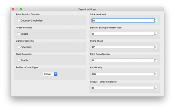
5.8.1 EXPERT SETTINGS
For fine tuning you can set the following parameters. Normally it is not needed to configure any of these parameters.
Rotor Rotation Direction
Parameter to determine rotation direction of the main rotor. In the most cases it is in the clock wise direction - parameter is unticked.
Stick deadband
Determines the area, around center stick, where the system does not recognize any stick movement. If channel readings are inprecise the value should be increased. This can be verified in the Diagnostics tab. This parameter does not replace the Exponential function.
Elevator pitchup compensation
If, during fast forward flight, the model reacts to inputs too rapidly or if the model pitches up, increase this value until this no longer occurs. If the helicopter pitches up abruptly, this could be caused by a cyclic range that is too low and/or too much collective pitch. In this case, you will have to increase the Aileron/Elevator range as high as the model can handle without any binding. If this doesn't fix the problem, you can add more pitch-up compensation.
Cyclic phase
The value indicates the angle by which the swashplate is virtually rotated.
For example a value of 90 will rotate the elevator to aileron. This feature is recommended for models with multi-blade rotor heads. For most other models, we recommend a zero value.
Pitch Pump Booster
To achieve flybar-like collective pitch behavior, you can increase the value until desired feeling is achieved. Remember that higher values are too demanding for power supply and servos on the model.
Signal processing
This parameter is used for operation on models with extreme vibrations that can't be eliminated in any way. This should be enabled only in cases when is absolutely necessary, because flight performance could be affected. It should increase precision of flight and also the precision of rescue and stabilization modes.
RPM Sensor Filter
In case that your RPM sensor has noisy output then RPM readout can be very unstable. This can lead to various problems with Governor. There may be a problem with spool up, flight mode switching or head speed jittering. To make RPM readout very precise, you may need to increase the value.
On the other hand, too high value can lead to a delay, that is unwanted for optimal Governor performance. So the value should be as low as possible while RPM readout is still precise. Variation of 1-20 RPM against the Requested RPM is optimal.
Autorotation Bailout rate
When performing autorotation the Bailout feature is available. The bailout is used to recover the headspeed faster than normally in order to achieve flying RPM. In this way pilot can regain full control of the model and continue in the flight. When using Spirit governor you can use this parameter to precisely set spoolup rate during the bailout. When Spirit governor is disabled, this settings has no affect.
Rudder - Control Type
With µSpirit units it is possible to enable support for the tail rotor driven by dedicated motor. In this case two ESCs are used, where Rudder ESC is connected at the CH4 port. Important thing is to set Limits/Rudder ESC - range appropriately since these are defining available Throttle range for the ESC from 0 to 100%.
Normally this parameter is available in the Setup Wizard.
5.8.2 TELEMETRY SETTINGS
ESC Telemetry is feature that enables transmission of the telemetry variables from the ESC to your radio. Covered in the ESC Telemetry page.
5.9 BACKUP TAB
Here, you can save the settings to your Spirit unit before powering off, you can also save the settings to your computer here, Should you need to reload them at a later date.
Profile
This section allows you to Save and Load complete settings of the unit to a specified file. If you have more than one of the same model, it is not necessary to carry out a complete setup again, just load the stored settings easily with the Load button.
Unit
Any changes to the configuration can be saved at any time to the internal flash memory of the unit.
To put all settings to a factory defaults, click Factory Settings.
Remember to save the settings each time you want to store the settings permanently. You must press the Save button. Otherwise, the changes will be lost after the Spirit FBL unit is turned off.
Bank Switching
In case that the Bank Switching is enabled, you can save the settings from single bank or even all banks. To see the differences between Banks you can use Bank Comparison feature.
5.10 UPDATE TAB
If you want to update the firmware, you can do so in this tab.
Firmware
First select the data file containing the firmware (*.4df) – Select button.Once the file is selected, press the Flash button. The upgrade progress will be displayed here. After completion, a confirmation dialog box should indicate a successful update.
Then, unplug the unit from its power source.
Upon the next start it will load with the newly flashed firmware.
Configuration of the unit is not changed, so you do not need to save/load it.
You can get firmware from: spirit-system.com.
6 BANK SWITCHING
This functionality allows you to switch between saved settings during a flight. Switching is done through the transmitter, so that channel's value is changed. This mean that a Bank can store one unique settings. The unit is able to store 3 different banks.
With a transmitter you are able to use a three position switch to switch freely between banks.
Bank switching is disabled by default, so you can decide whether it is useful in your application. You have to activate it by the assignment of Bank function in the General/Channels window. Generally, it is assigned to channel 7.
- Bank 0 – active in range of lower third (impulse under 1400μs).
- Bank 1 – active in range of mid third (impulse between 1400μs to 1640μs).
- Bank 2 – active in range of upper third (impulse above 1640μs).
Initial settings for Bank 1 and Bank 2 are equal to Bank 0. Bank 0 allow you to configure all parameters, while Bank 1, 2 does not allow to set main parameters. For safety, Bank 1 and 2 does not allow you to set any main parameters.
The Bank switching is great for switching between flight styles, sensor gains for low or high RPMs, for slow acro or 3D. Alternatively it can be used just for tuning your settings.
If the software (or a transmitter integration) is connected with the unit then bank switching by assigned switch of the transmitter is temporarily disabled. Then, Bank switching is performed using the software in bottom part of the window. When a bank is switched using the software it is necessary to save your settings to the unit before you switch Banks, or your settings will be returned to the previous (unchanged) state.
Always close the software or any connected app before flying. Otherwise it will be not possible to change Banks by assigned switch of your transmitter.
To verify that the Bank switching is working properly, please start the software and look at the Diagnostic tab. There you can see Bank indicator with the channel bar. Try to change position of assigned switch. If everything is correct, you will see that the Bank number will change there.
7 GOVERNOR
From firmware version 1.2 governor feature is available! You can use this feature instead of internal governor from your ESC or other governor. It is designed to work with electric, nitro and gasser helicopters. This can make flight performance even better because of constant head speed.
To achieve proper function it is very important to configure your ESC and then the unit. First from all make sure that internal governor is disabled in the ESC.
It is necessary to disassemble rotor blades from your model prior to the governor setup. Do not make any adjustments with motor turned on.
Governor feature can be used with the following receiver types:
Spektrum DSM2/DSMX, Futaba S-BUS, Jeti EX Bus, SRXL/SUMD.
It is necessary to use throttle output from the unit when using governor. Throttle output is at the AUX port. You must connect the ESC or throttle servo there.
7.1 Sensor Wiring
Signal from a RPM sensor should be connected to the PIT pin (middle pin of the ELE/PIT/AIL port - Spirit and Spirit Pro; P pin, red wire - μSpirit).
- ESC with RPM output
- For electric helicopters the best and the easiest solution. You can use RPM output cable that is present on the ESC.
- ESC without RPM output
- In case that your ESC has no RPM output you will need a separate RPM sensor that can be connected to phases of the motor. Important is to power the sensor properly. Voltage can't exceed allowed level for the sensor. Recommended voltage range can be obtained from the sensor manufacturer. In case that the sensor require 3.3V you can connect it to the satellite connector in the unit (Details in the following photo). You can also use the Spektrum adapter.
- In case that the sensor is powered improperly it can be damaged along with the unit.
- Magnetic sensor
- For Combustion helicopters is necessary to use a sensor working on principle change magnetic field. In case that your ESC has no RPM output you will need a separate RPM sensor that can be connected to phases of the motor. Important is to power the sensor properly. Voltage can't exceed allowed level for the sensor. Recommended voltage range can be obtained from the sensor manufacturer. In case that the sensor require 3.3V you can connect it to the satellite connector in the unit (Details in the following photo). You can also use the Spektrum adapter.
- In case that the sensor is powered improperly it can be damaged along with the unit.
Red (+3.3V), Brown (GND).
7.2 Prerequisites
Electric
- Set throttle range in your transmitter so that 0% and 100% throttle position matches with value of the throttle bar in the diagnostics tab. This can be done by Subtrim function in your transmitter and/or Travel Adjustment function.
- Re-calibrate throttle range according to instructions of your ESC. In the most cases it can be configured by powering the model with throttle stick with 100% throttle and then by moving the stick down to 0%.
- If possible, configure fast spoolup mode in the ESC so the governor will be unaffected.
Nitro / Gasser
- Set the throttle range in your transmitter so that 0% and 100% throttle position matches with value of the throttle bar in the diagnostic tab. This can be done by Subtrim function in your transmitter and/or Travel Adjust function.
7.3 Activation
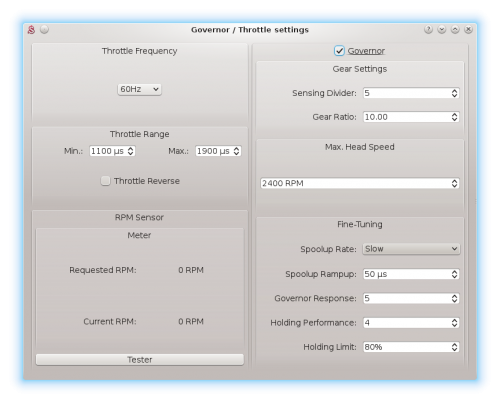
To activate Governor feature in the unit, you will need to assign Throttle function in the General tab/Channels. Then you will be able to enter Governor Settings in the General tab.
7.4 Settings
First from all basic settings are necessary so the governor can control the head speed correctly.
Throttle frequency
To achieve the fastest governor reaction it is necessary to set the highest possible frequency. For ESC it could be only 60Hz, but mostly all can work even with 200Hz. If you are unsure, please contact manufacturer of the ESC. For combustion helicopters it is max. operating frequency of the throttle servo.
Throttle Range
This parameter can affect output from the unit so you can fine-tune ranges precisely. For electric helicopters this parameter is optional. But in case that your ESC does not allow to calibrate throttle range correctly, you can do so here. For Nitro and Gasser helicopters you have to configure it always so the Throttle servo range matches range for the motor.
Throttle Range - Min.
Value of the lowest throttle signal. Default value: 1100 μs. For electric helicopters this value should be specified by manufacturer of the ESC. It is often specified in value of miliseconds (ms).
Parameter is optional - you do not have to change it if your ESC support the throttle calibration (e.g. by sticks).
You should set the lowest position when the motor is not spinning up anymore – is halted. While configuring this, the motor can start so you have to be very carefull.
Throttle Range – Max.
Value of the highest throttle signal. Default value: 1900 μs. For electric helicopters this value should be specified by manufacturer of the ESC. It is often specified in value of miliseconds (ms).
Parameter is optional - you do not have to change it if your ESC support the throttle calibration (e.g. by sticks).
The value should be configured to match with 100% throttle output programmed in your ESC or full throttle of the motor. If this parameter is not high enough you will be unable to tune Governor because there will be not enough room to compensate high loads. If configured too high then you can observe that after high load head speed will not drop immediately but can be there even for few seconds.
Throttle Reverse
Especially for Nitro and Gasser motors you can set correct compensation direction for the servo here.
Gear Settings - Sensing Divider
Electric motor: Motor poles / 2. For a 10 pole motor set divider to number 5. Mostly configured to 3 – 5.
Nitro/Gasser motor: Number of all active magnets. Mostly it is 1 – 2.
Gear Settings - Gear Ratio
Gear Ratio of the helicopter between the main wheel and pinion of the motor. For example: 120T main gear / 12T pinion = 10.
Max. Head Speed
Configure max. head speed that should be achieved with 100% throttle curve. For example: If you know that you won't exceed 2500 RPM then you can set the value to 2500. With 80% throttle curve your head speed will be 2000 RPM (2500 * 0.80 = 2000).
Fine-Tuning – Spoolup rate
Configure speed of the motor spoolup. For initial tests we recommend Slow spoolup rate.
Fine-Tuning – Spoolup Rampup
Value that will be added at the beginning of motor spoolup – when Hold is turned off. If the spoolup is not smooth, i.e. motor will start with a kick, the value is too high. If the spoolup has a delay, the value is too low. Default value of 50 μs should work fine in the most cases.
Fine-Tuning - Governor Response
This parameter is the most important one to achieve fast and proper response of the governor. It determine how fast the governor should react to a short-term load. Thus optimal settings are required. If configure too low or too high, rudder will not hold properly and can oscillate. Governor can greatly affect rudder performance so you can achieve better holding behavior. Too high value will result in overspeeding during e.g. pitch pump.
Fine-Tuning - Holding Performance
Determine how well the head speed is maintained during a long-term load. If value is too low then during e.g. tic-toc maneuver head speed can drop gradually. In case it is too high then after the tic-toc head speed can be higher than necessary and can even return to requested RPM with noticeable delay. It is better to start governor tuning process with low value.
Fine-Tuning - Holding Limit
Prevents from prolonged overspeeding after demanding maneuvers. If head speed is higher than requested after demanding maneuver then by decreasing percentage value it is possible to shorten or eliminate this odd behavior. If Limit value is too low then Holding Performance will not affect Governor performance. It is recommended to use 80% for the most helicopters. Usually combustion helicopters might need to decrease the Limit. Changing the Limit as the last parameter of the Governor is recommended - once a proper Governor Response and Holding Performance values are configured.
7.5 Transmitter
Flat Throttle Curve above 50% is necessary in order to use Governor feature. Under 50% Governor is immediately disarmed and instead motor will be driven directly by throttle curve. As soon as it will exceed 50% spoolup procedure is engaged until Requested RPM is reached. Only when Flight log will show Governor was Engaged then Governor is maintaining Head-Speed. If this message is not present it mean that Governor is still in the spoolup procedure.
In order to achieve different Head Speeds on demand you can set different flat curves (for example for each flight mode).
Governor can be deactivated in flight by switching to a Bank where Governor is disabled in the Spirit Settings. It can be also re-activated by switching back to a Bank with enabled Governor.
With a combustion motors we recommend to go from Idling (Throttle Curve around 10%) directly to 50% flat curve and above. This will trigger smooth spoolup.
7.6 Fine-Tuning Procedure
Firstly you have to finish basic setup including Max. Head Speed. Throttle curve in the transmitter must be FLAT. We recommend to set the throttle curve for example to flat 70%, 80% or 90%.
After disarming Throttle Hold you should immediately see Requested RPM in the software – this is desired head speed that should be maintained. Current RPM is head speed that is currently on the rotor head. If Current RPM is not calculated properly, then there is a problem with Gear Settings. In case that you can see zero or random Current RPM value then there is a problem with RPM Sensor and must be fixed.
Performance tuning procedure
We recommend to set the following values for the beginning:
- Governor Response: 5
- Holding Performance: 1
- You should start with increasing the Governor Response. You can do so until RPM is constant enough while doing aggressive collective pitch changes during hovering. When you will notice an overspeeding (RPM is higher than initially was) then the value is too high. In case that the value is too low or too high then the rudder performance can be affected negatively as well.
- When the Governor Response is well tuned, you can continue with increasing the Holding Performance parameter. In case that the value is too low, you will notice poor holding performance during demanding maneuvers with longer duration such as loop or tic-toc. If the value is too high, you can observe that the head speed is unstable even during stationary hovering.
Governor Response: 6 and Holding Performance: 5 may work fine for wide range of the helicopters.
- Throttle calibration of the ESC is possible only if the Governor is disabled in the unit.
- For throttle curve under approx. 50% governor is inactive – throttle is controlled directly.
- You should see “Governor was Engaged” event in the log after spoolup with enabled governor.
- Governor Bailout function can be activated whenever the throttle signal is higher than 1250 μs which is approx. 12% throttle curve. If the signal is lower then smooth spoolup sequence is activated.
- In case that the Current RPM value is 8000 RPM measurement is out of range. It may be needed to change count of the active magnets.
- If governor does not react correctly during Throttle Curve changes or even during spoolup, it is most probably result of an excess noise in the RPM sensor or connection. You may consider to use a proper shielding. Increasing value of the RPM Sensor filter in the Expert settings can solve the problem.
7.7 Sensor List and Troubleshooting
List of supported RPM sensors and their wiring is available on the Governor page.
You can also find there solutions for a various problems related with the Governor.
8 SOFTWARE KEYBOARD CONTROL
For fast and easy configuration we have implemented keyboard controls in the software.
| Shortcut | Function |
| F1 to F10 | Switch between tabs. |
| ESC | Exit current window. |
| CTRL + S | Save settings to the unit. |
| CTRL + P | Save profile to your computer. |
| CTRL + L | Load profile from your computer to the unit. |
| CTRL + W | Connection settings for the Wifi-Link module. |
| Numpad 0, 1, 2 | Switch between banks. |
| Tab | Switch between parameters. |
| Space | Select parameter / option |
| Arrows | Increase / Decrease value. |
| Page Up / Page Down | Increase / Decrease value by tens. |
| Home | Set the lowest value. |
| End | Set the highest value. |
